Bipedal Walker
Project Overview
Designed and built a robotic leg system as part of a project focused on developing modular, functional, and mechanically efficient joints. The robot features custom 3D-printed components, heat-set inserts, and precise servo motor control. Explored various motion patterns, addressed fit issues, and implemented robust error-handling in code. Applications include advancing robotics for confined spaces and automation. Demonstrated proficiency in CAD, motion planning, and hardware integration throughout the development process.
Development Timeline
Week 1: Concept Sketches
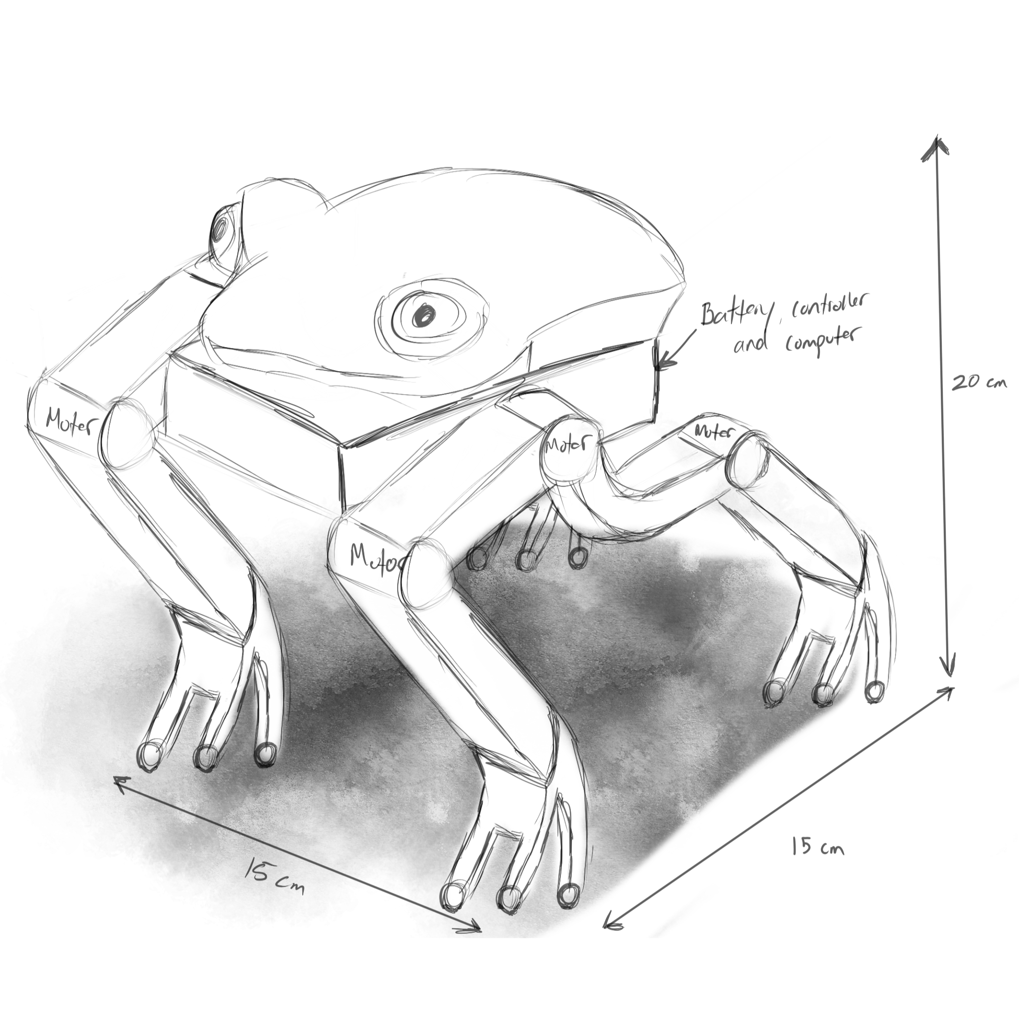
Starting off the design process, a few potential designs were to be devised, sketched out in pencil and paper. The requirements for the project were that the robot make use of legged locomotion and be comprised of 8 rotational motors. As part of each of the 3 sketches presented, estimated total motor energy consumption and battery life was included to provide as much detail as possible additional to the placement of electronic components and drawing techniques that bring realism.
The first concept is a three legged robot that utilizes 8 motors, 6 for the two legs in the back and 2 for the front leg. Inspiration for this concept came from a Star Wars vehicle called AT-AP. This was the winning concept.
The second concept is a six legged robot that also utilizes 8 motors, 1 for each leg and 2 to help the movement mechanism work. Inspiration for this concept also came from a Star Wars vehicle called AT-TE.
The third concept is a four legged robot makes use of 6 motors. The legs come in pairs, allocating 3 motors for each pair. AI was put to use to generate potential ideas, creating a frog-like robot that was deemed promising.
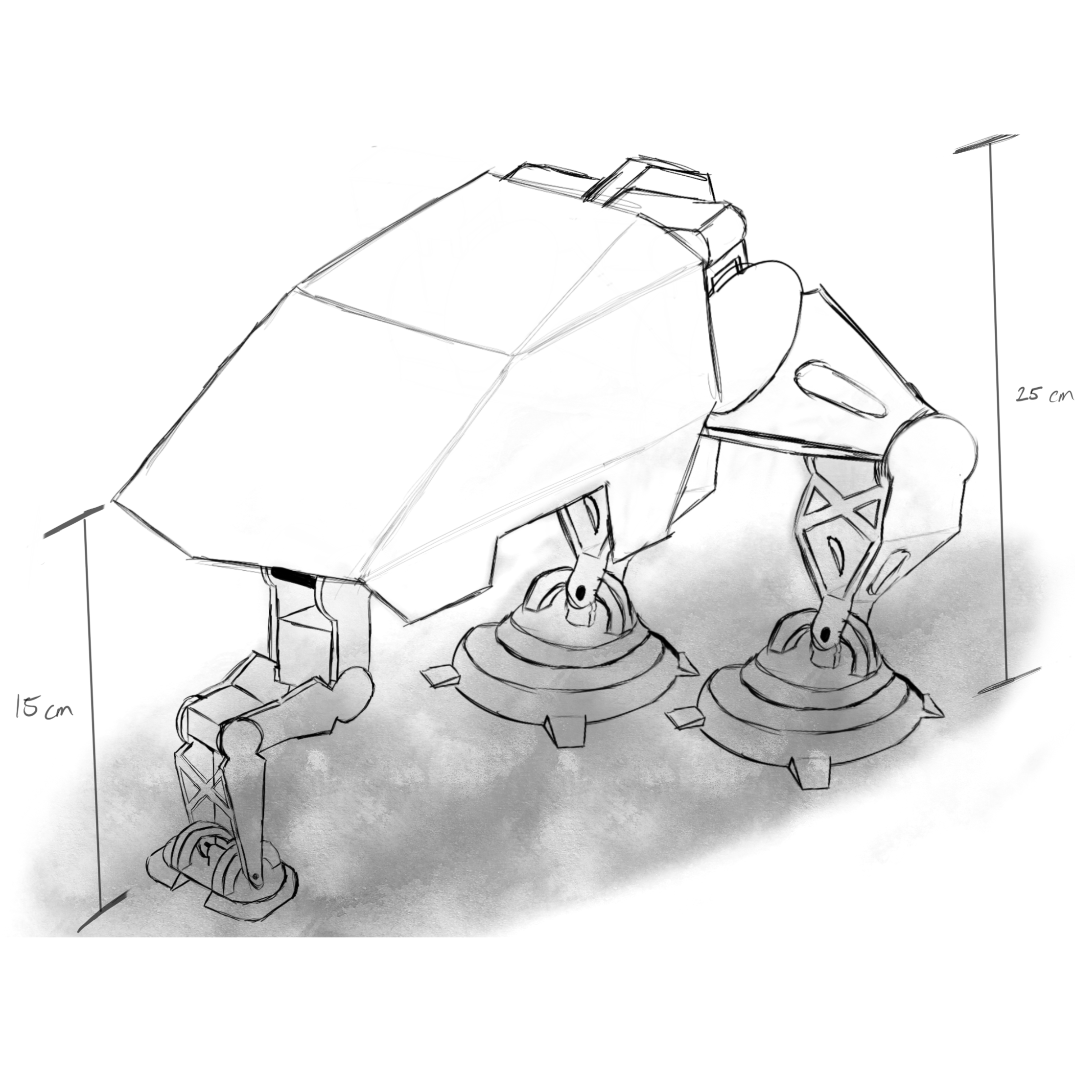
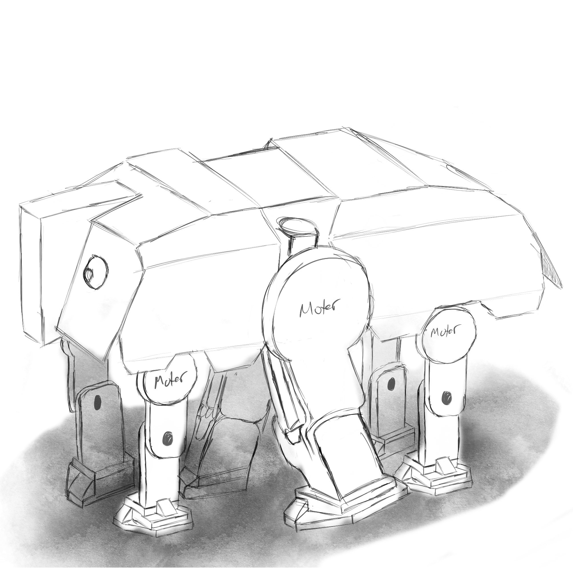
Sketch of the first concept
Week 2: Preliminary CAD
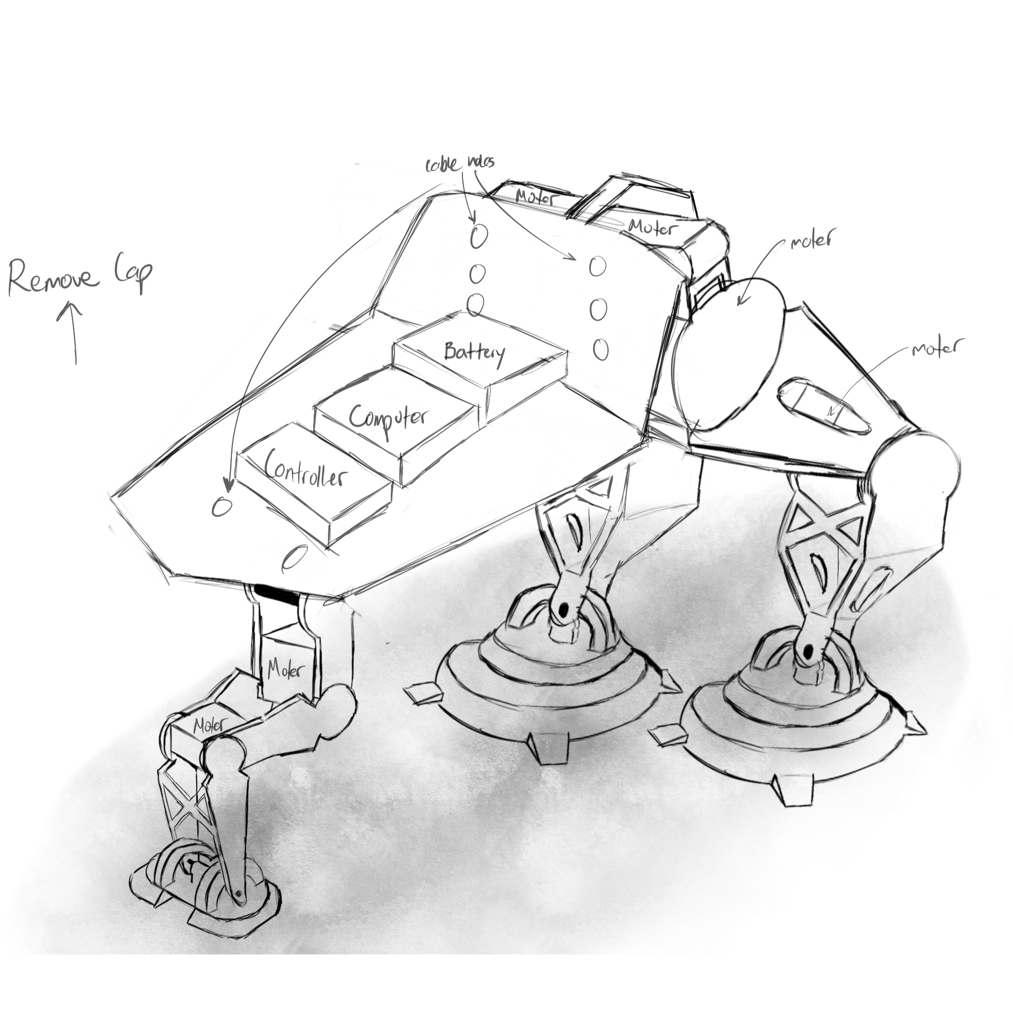
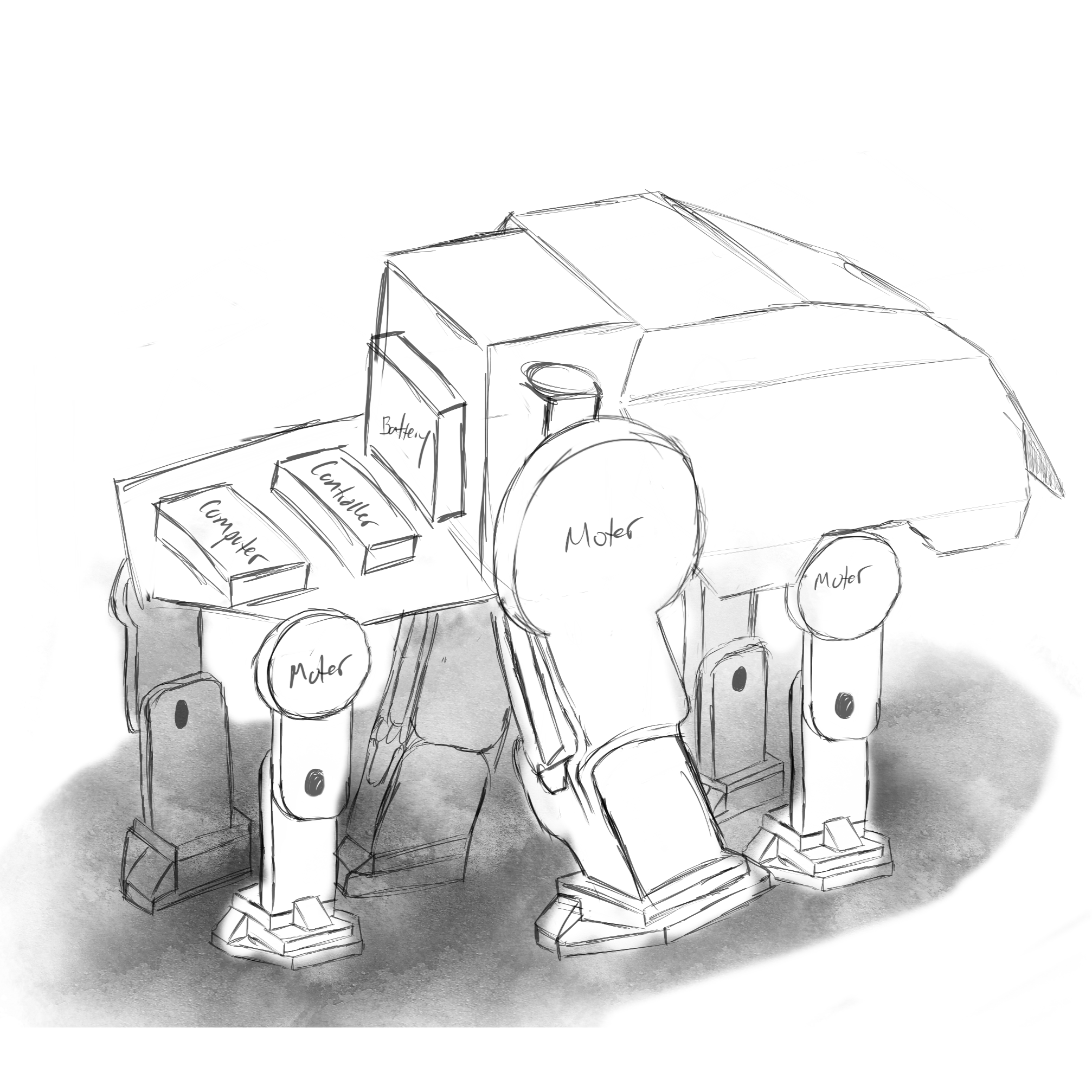
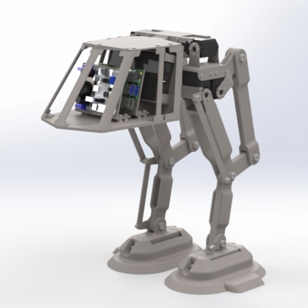
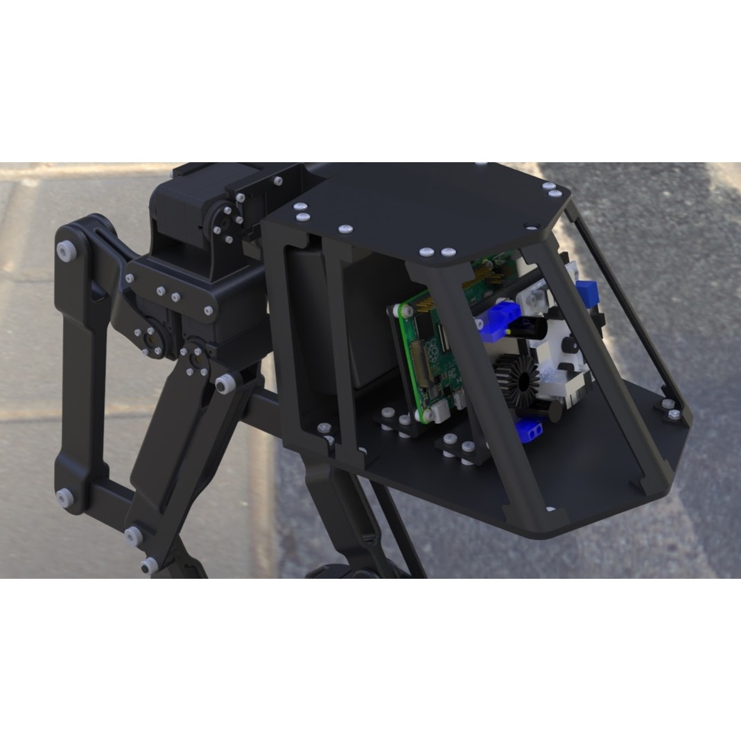
Building on the initial sketches of the winning concept from Week 1, the next step was to create a preliminary CAD model to study the feasibility of the winning design. Using downloaded CAD models for components such as the Raspberry Pi, motors, controller board, and battery, the focus was placed on achieving an arrangement of all the major subsystems of the robot concept. The winning concept was revised to fully integrate all the subsystems into one cohesive model.
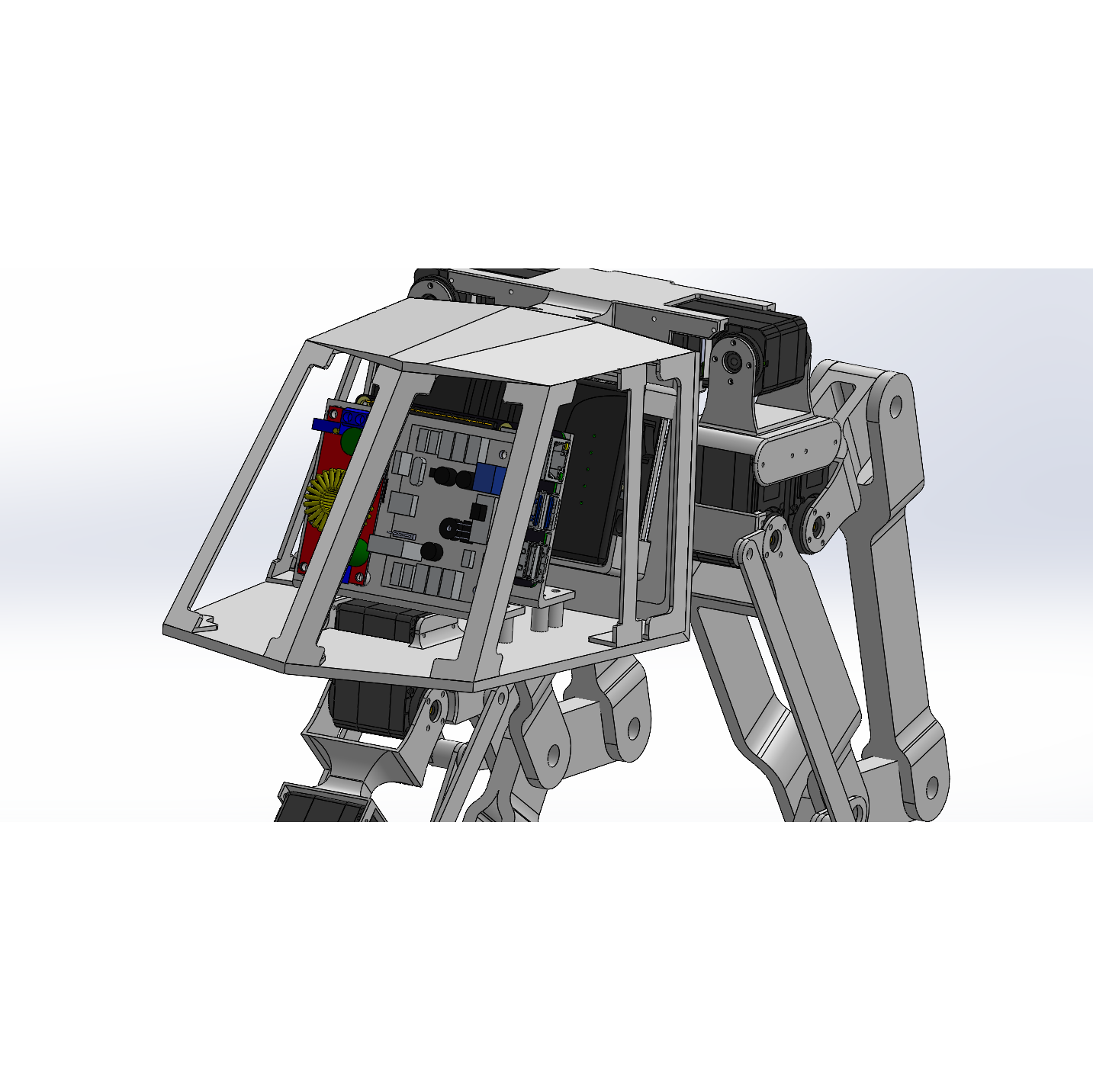
As part of the preliminary CAD model, the location and placement of the electronics were essential for the construction of the overall sructure of the robot, which was already planned ahead in the concept drafting step. Moreover, the geometry and kinematics of the robot body and limbs is higlighted to ensure that the robot moves correctly and that the design appears stable. Details such as fasteners, mounts, and cable routing were left out to keep attention on core feasibility.
This stage not only validated that the selected concept could be realistically assembled, but also helped identify areas for refinement and improvement moving forward. Finally, the robot was given a working name to help solidify its identity as the design progresses: Tri-nsport Robovehicle.
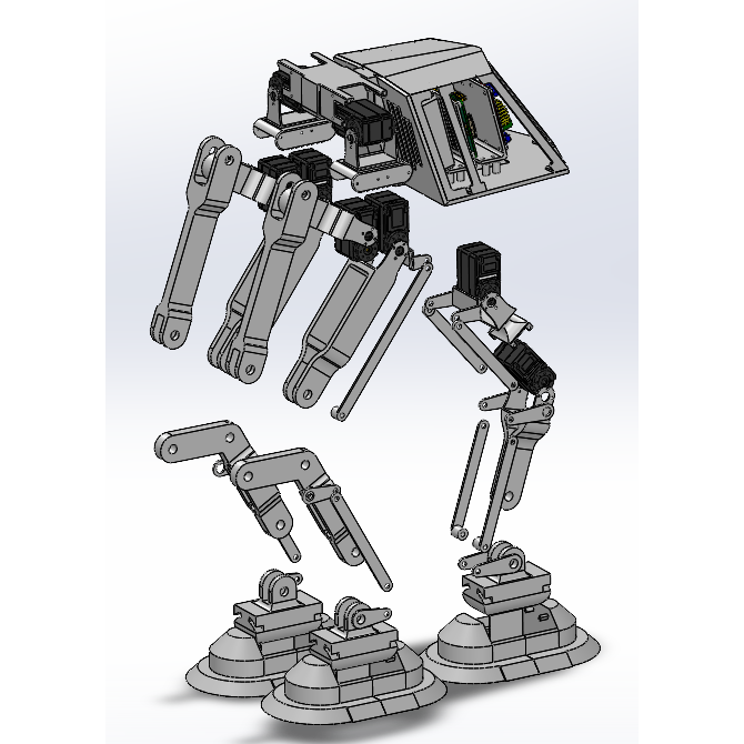
Render of the Preliminary Design
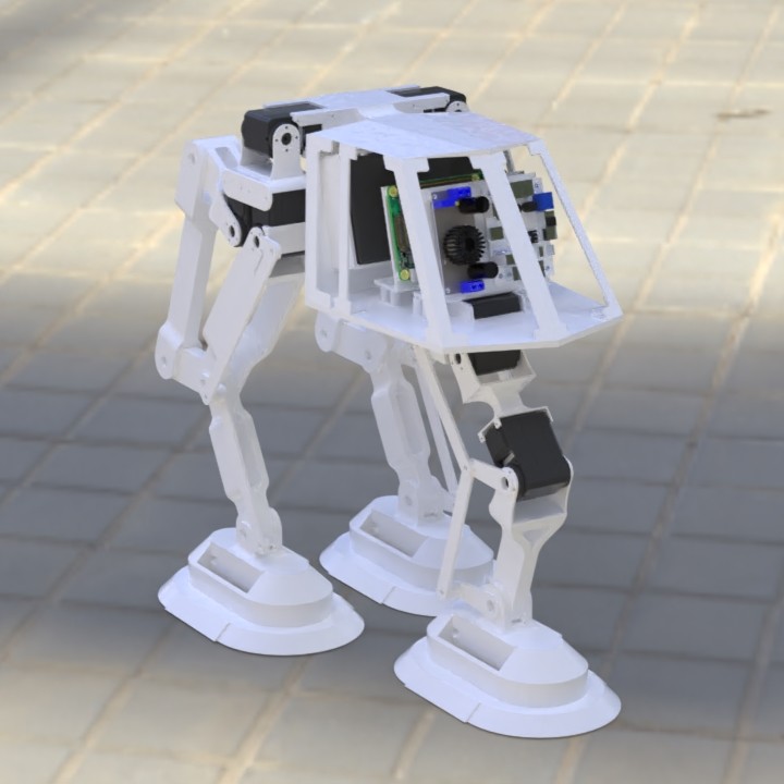
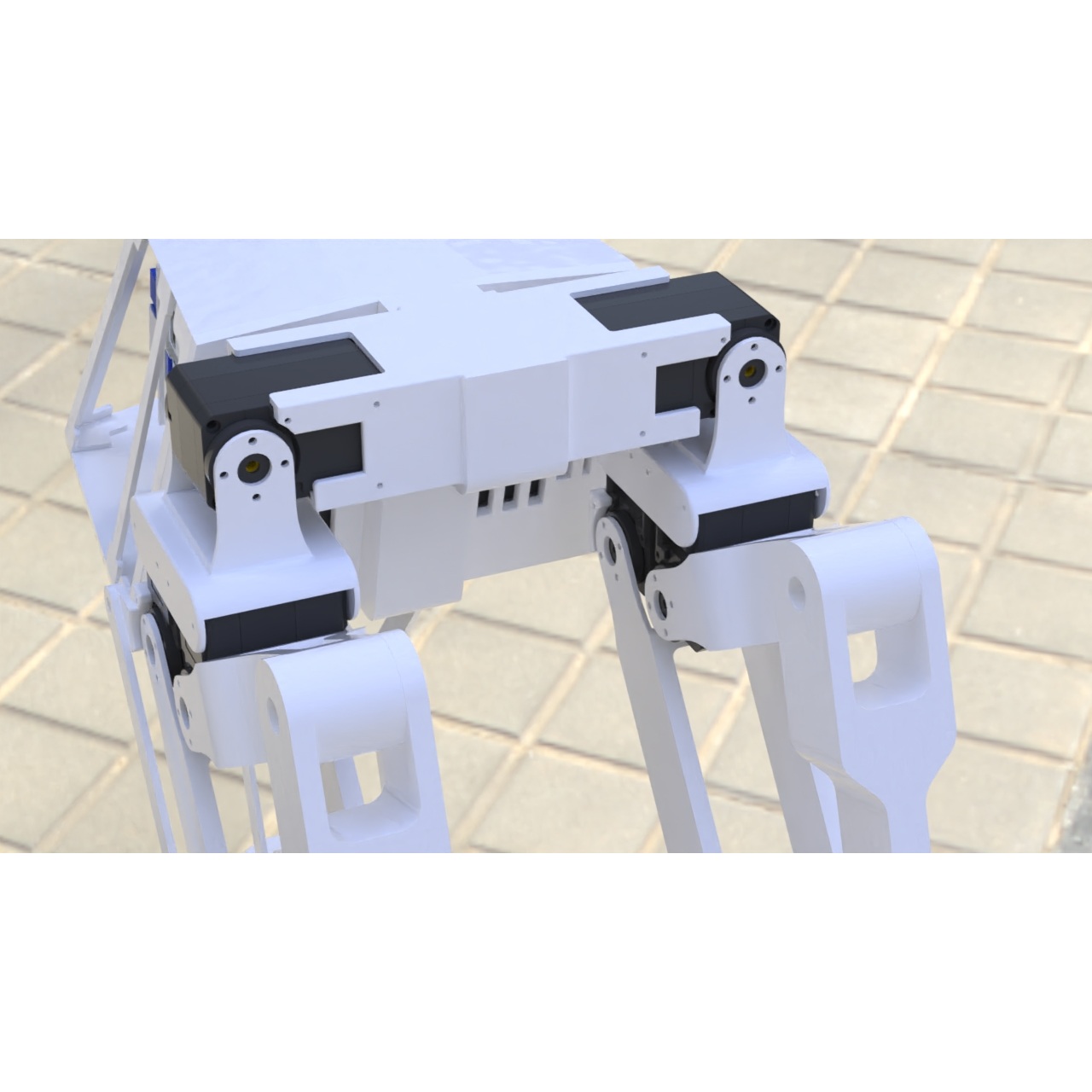
Week 3-4: Detailed CAD
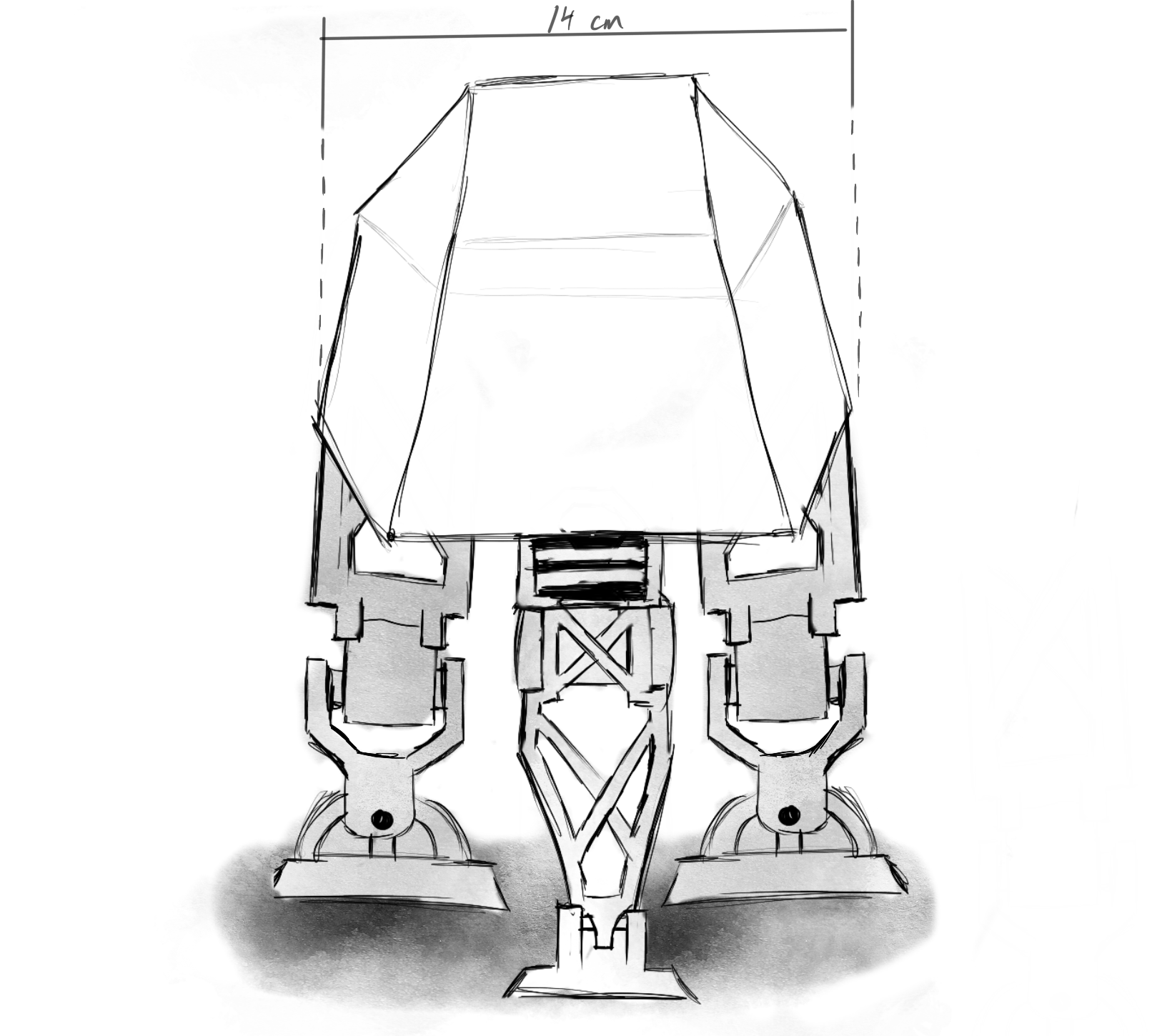
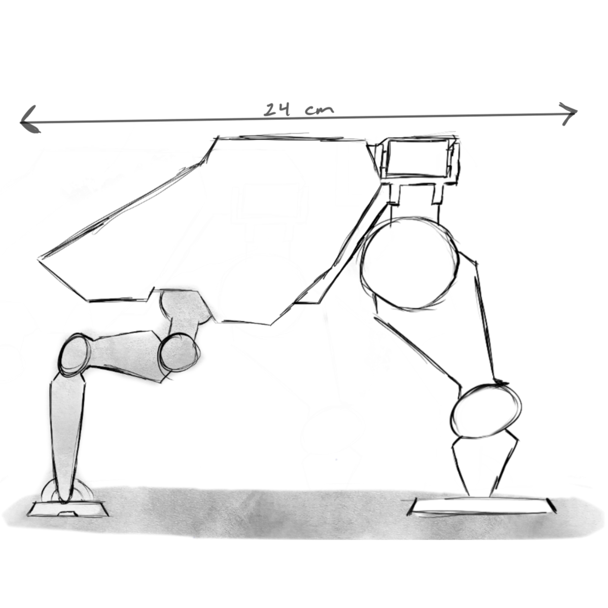
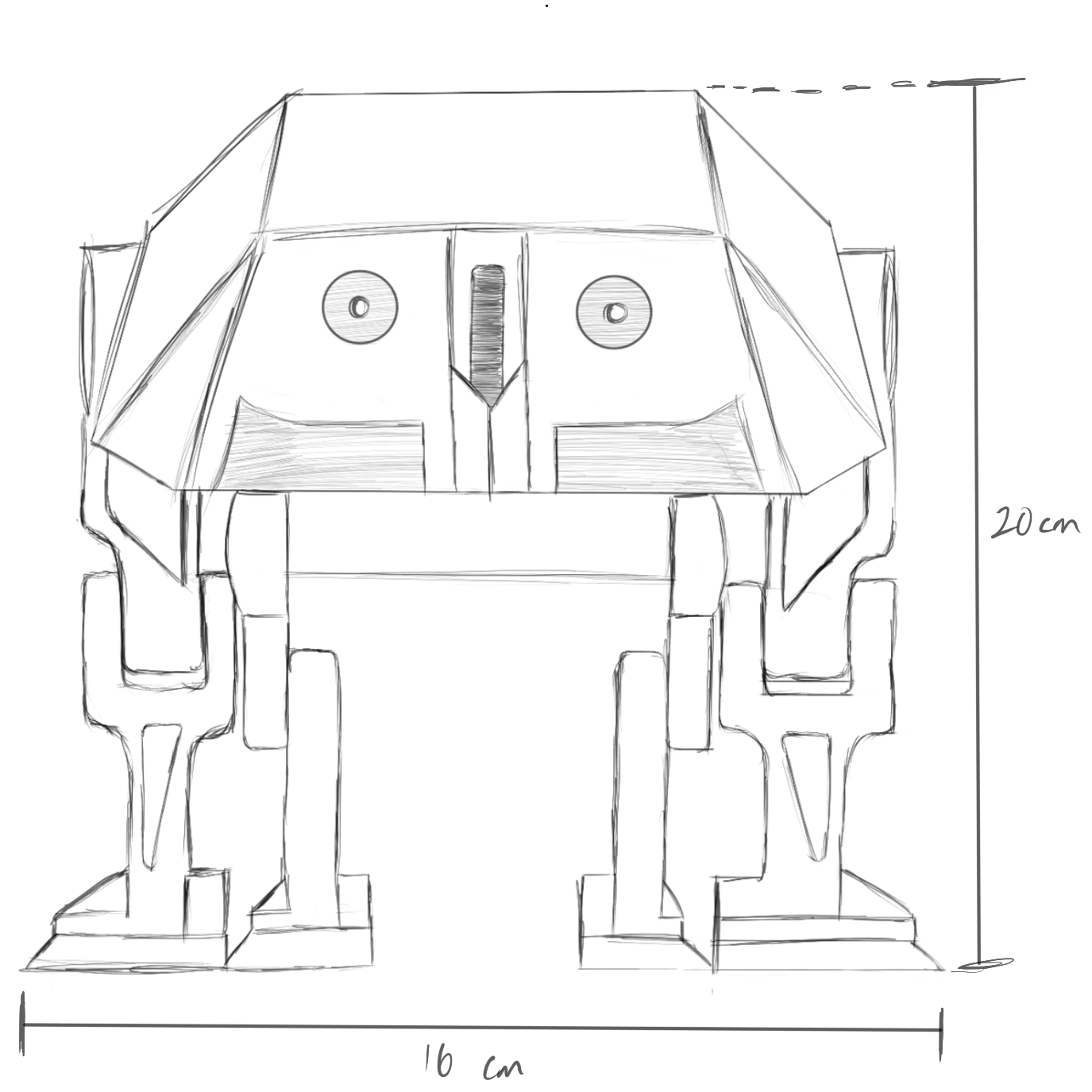
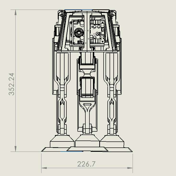
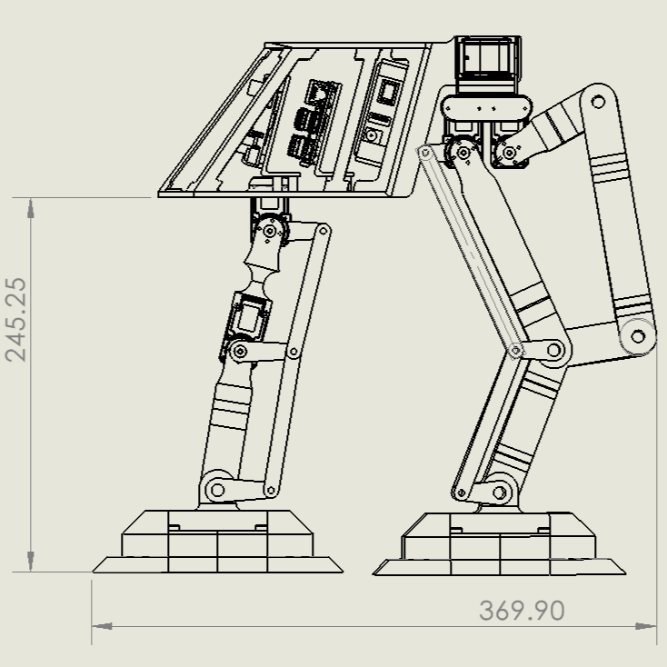
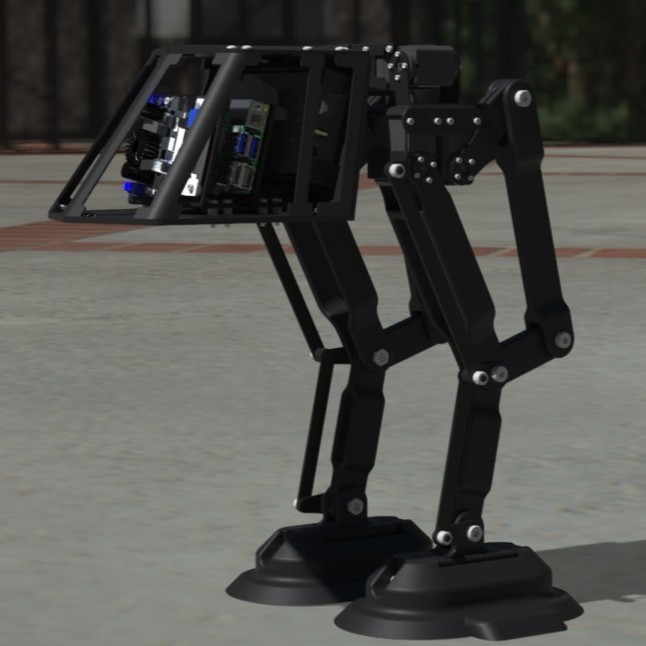
At this stage, the design went through major changes. The idea of making the robot have three legs was scrapped and it was decided that it would only have two legs for locomotion. The new design iteration gave the robot a new name: Bipedal Walker.
This big design change presented new challenges but also the opportunity to learn more about bipedal robots. The inspiration for the overall concept comes from a hybrid robot that is both a 3-legged and 2-legged robot, using the third leg for stability when standing still. Therefore, the 2-legged version was favored to provide a more concrete walking gait. The removal of the third leg would improve battery life and reduce overall weight of the robot.
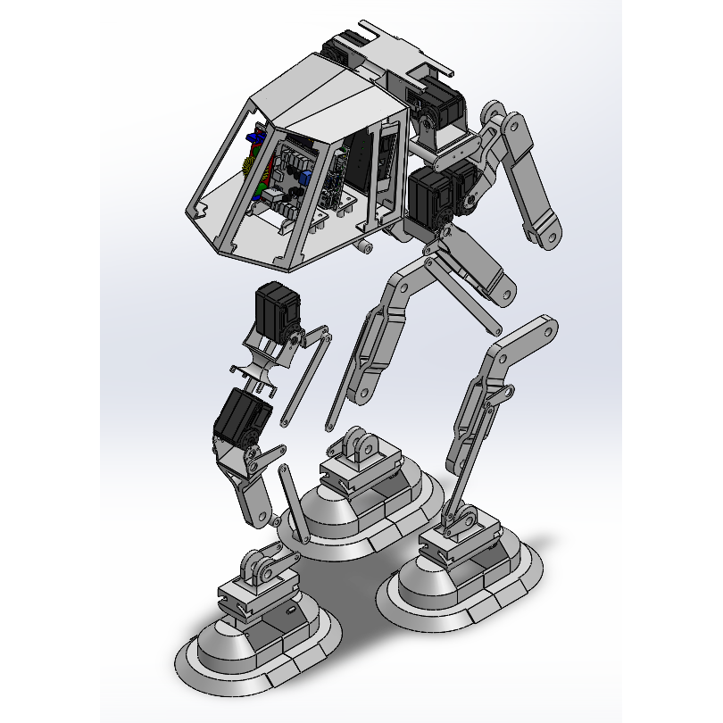
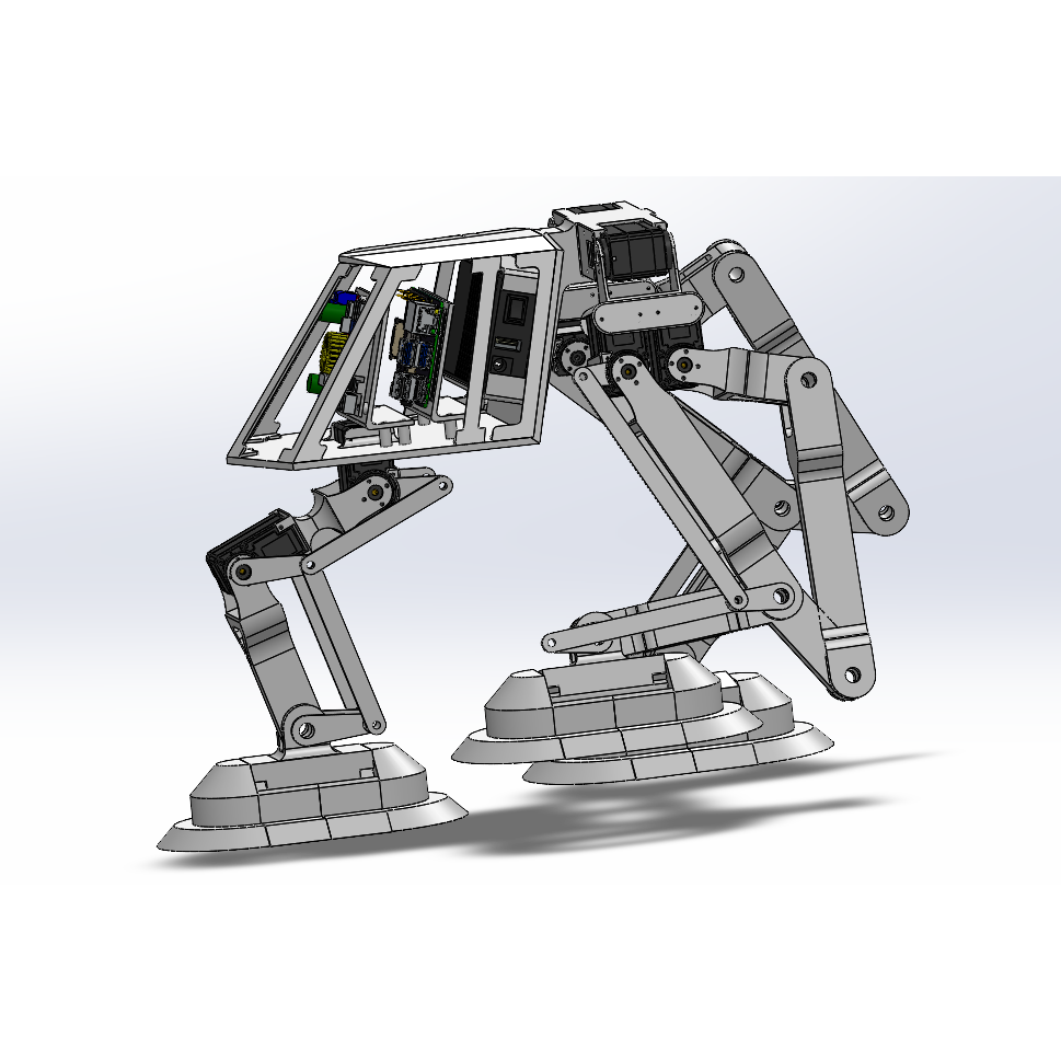
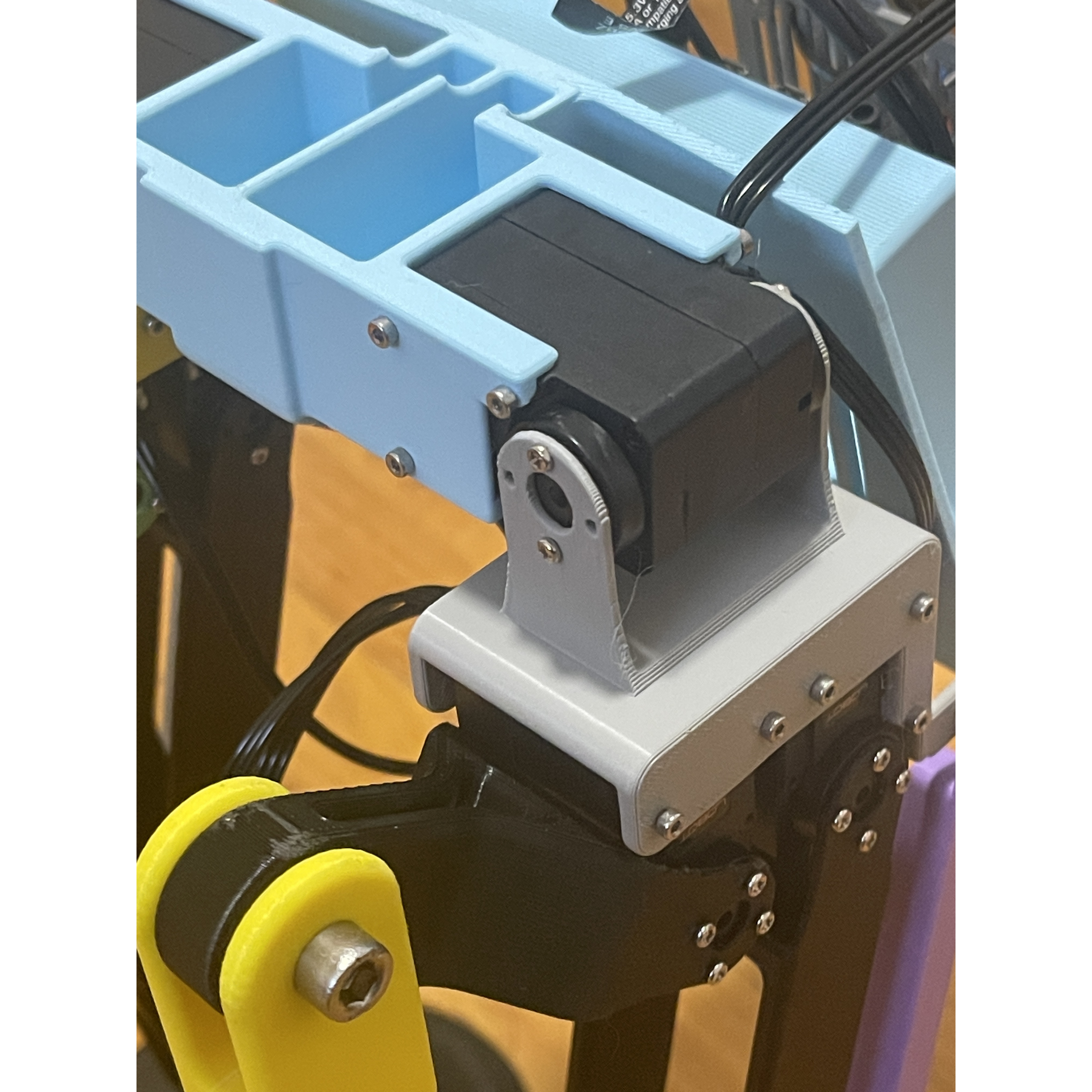
Now that the design is more concrete and no significant design changes will occur, the new CAD model is now equipped with more detail. Fasteners are shown throughout the model, showcasing how all parts in the robot will be attached to each other. It was prioritzed to use few different types of fasteners to reduce the size of the bill of materials and to not rely on complex fastening techniques. Additionally, as part of the batch of new details, the robot was given a more organic look by reducing the number of straight edges.
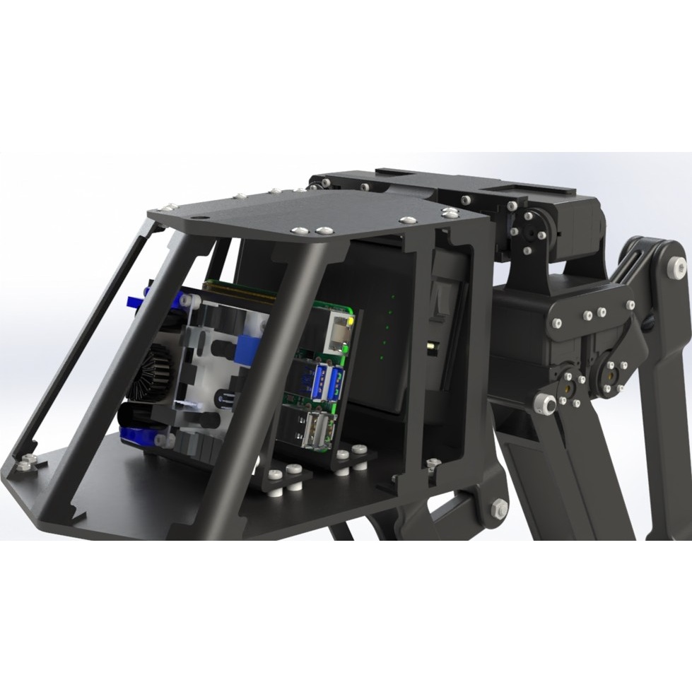
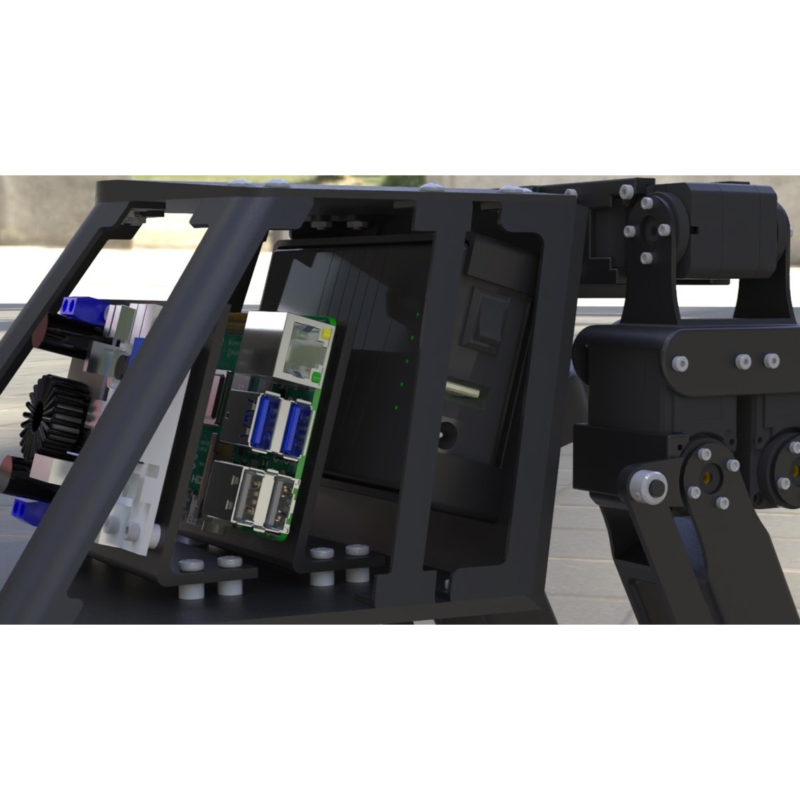
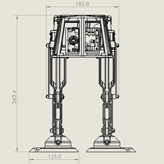
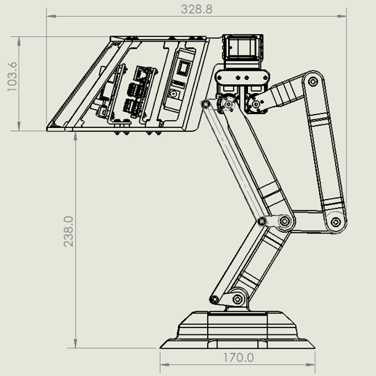
CAD model of the Detailed Design
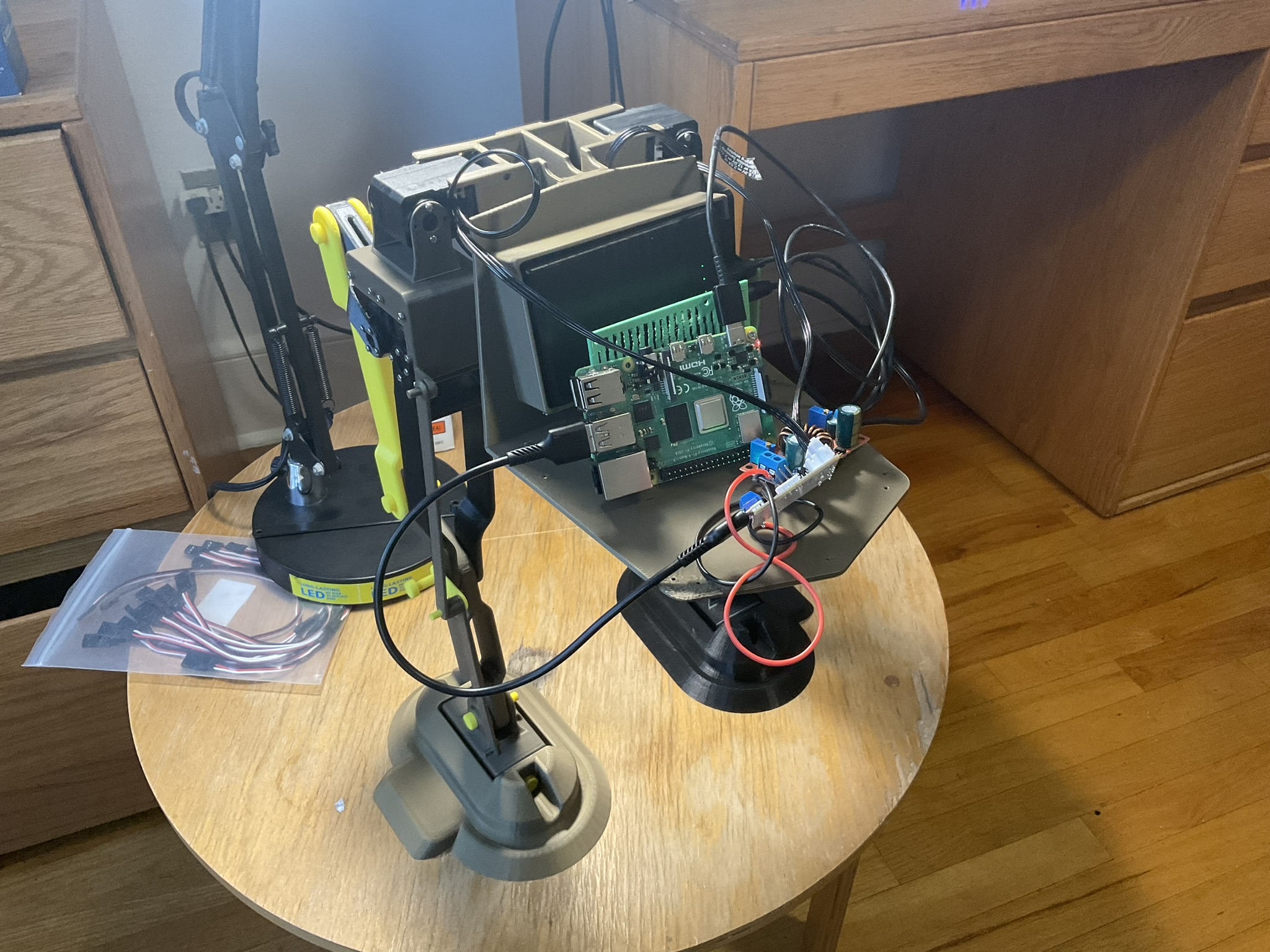
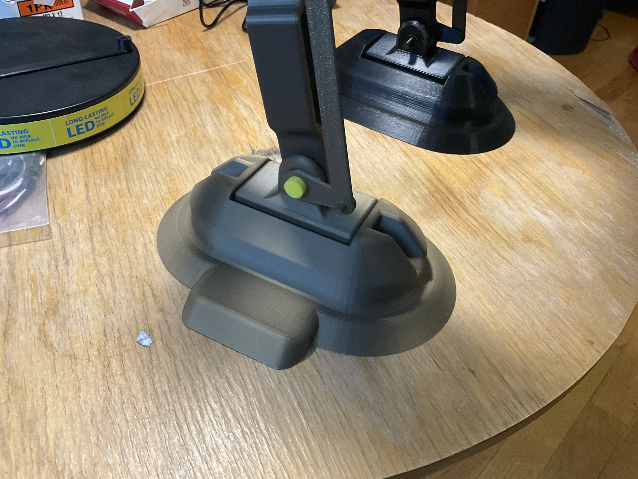
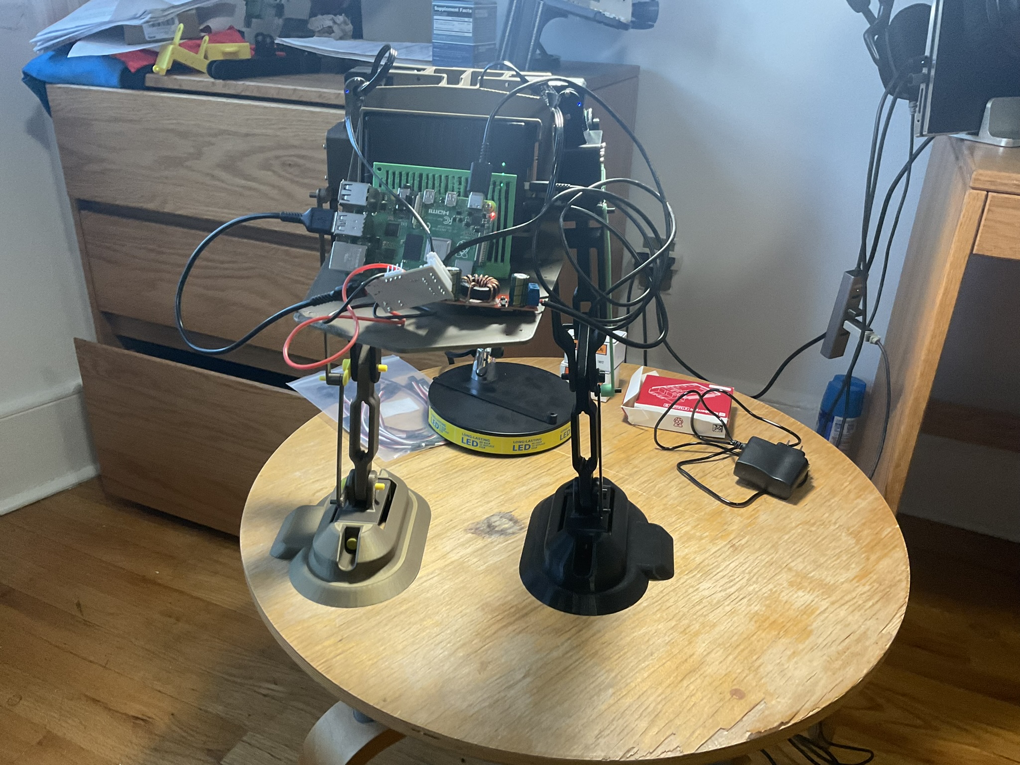
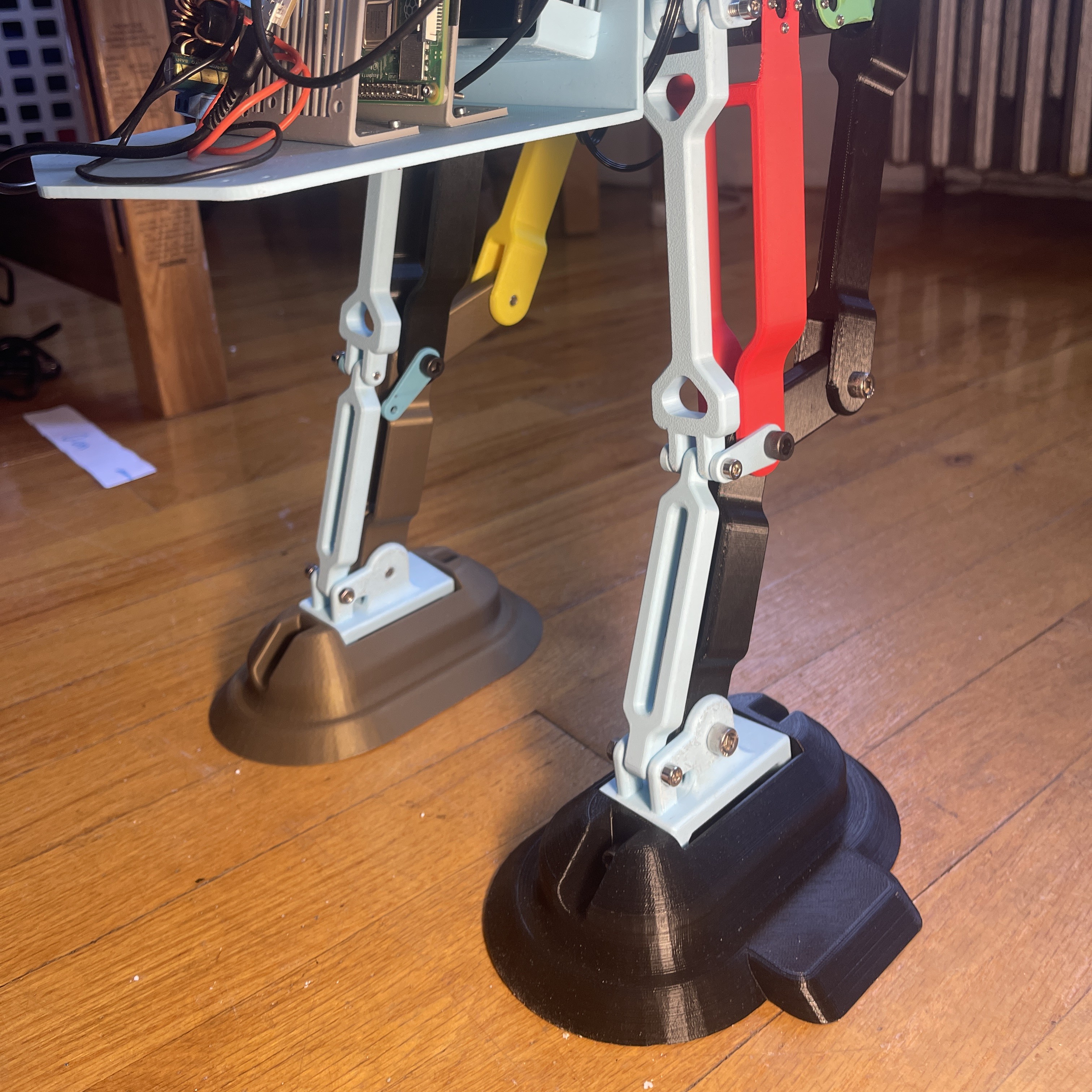
Week 5-6: Partial 3D Printing & Form-fit Testing
Now that the design of the robot is more concrete and finalized, it is imperative to test the functionality of the legs, the means of locomation for the robot. At this stage, the goal is to manufacture and verify initial power, control, and motion of legs, while also updating the CAD model as necessary. In this stage too, the control software was initially set up and devised to allow the testing of the leg. The experimation of the control software in this stage was essential because it helped guarantee a working leg before fully commiting into the manufacture of the full robot. Check out the video of the leg working in its initial stages.
The means of manufacture for the non-electronic and non-fastening parts of the robot are provided by 3D printers. Even though 3D printing allows the complexity of parts to increase, because of time constrains, most manufactured parts were redesigned and updated with manufacturing times in mind.
The CAD model was to be kept up to date with any changes. It was made sure the CAD model matched the configuration at which the physical leg was assembled in. Problems were determined and were documented, such as form and fit issues due to printer resolution. As issues were noticed, new iterations of parts were outputted as fast as possible to resolve movement problems or interferences.
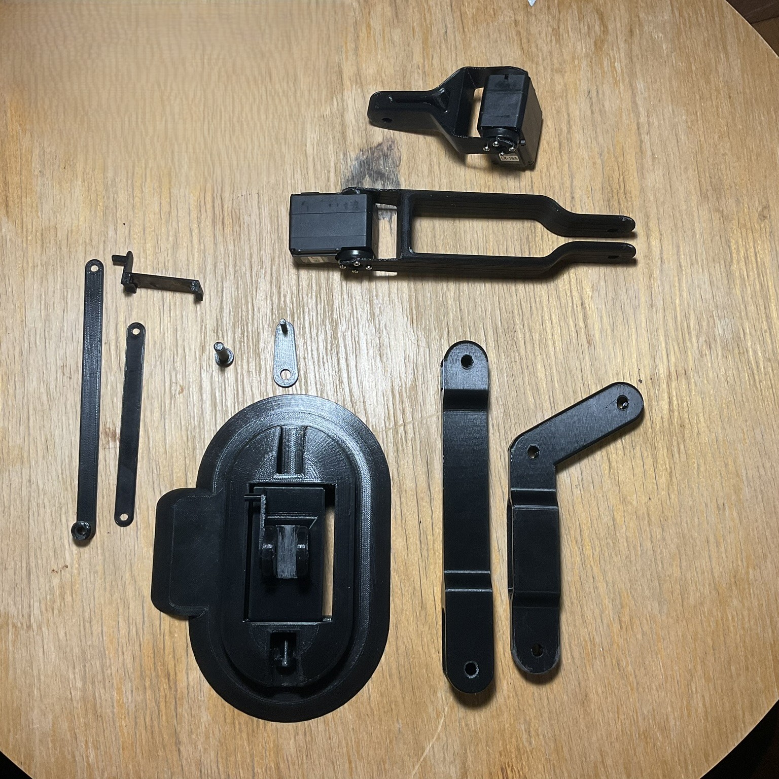
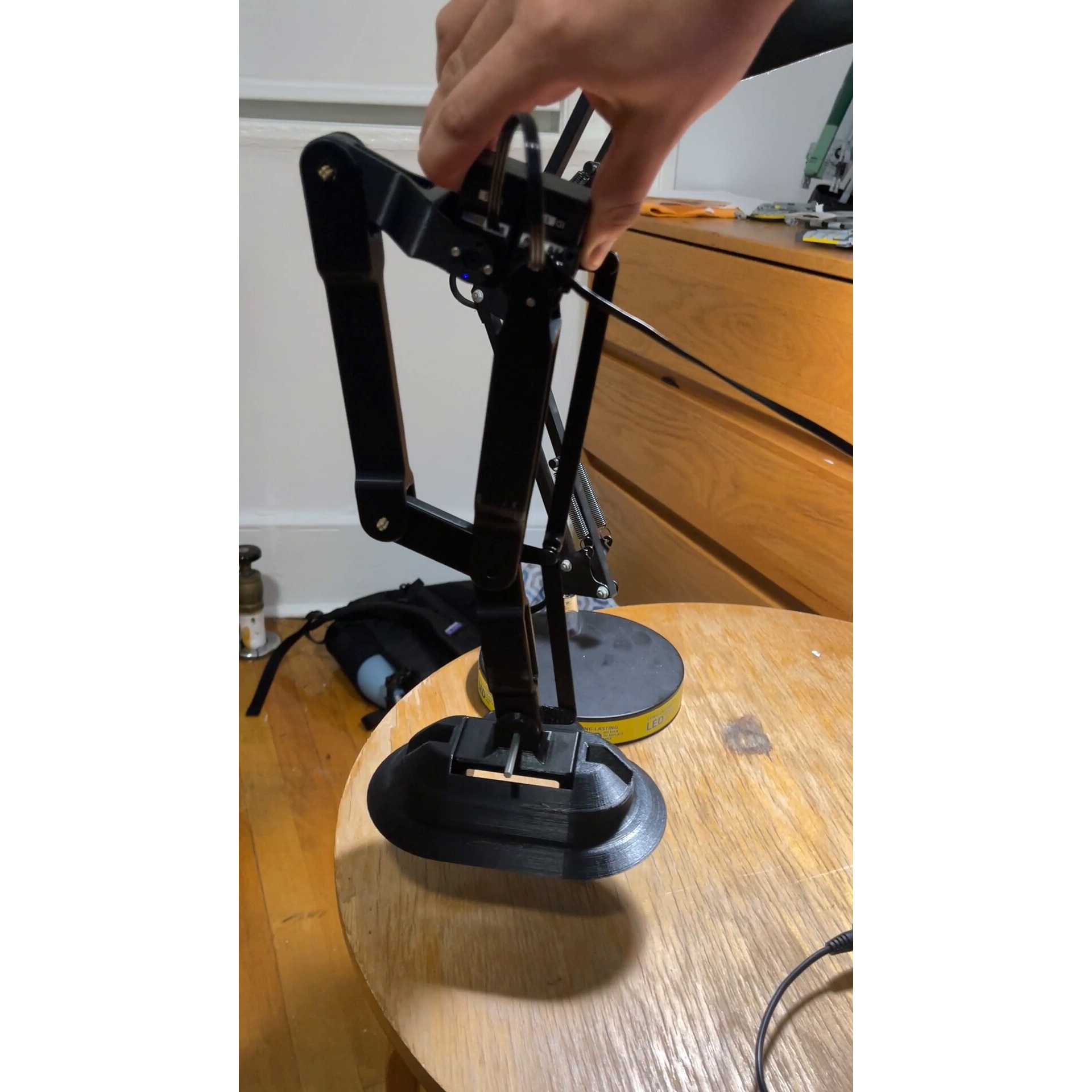
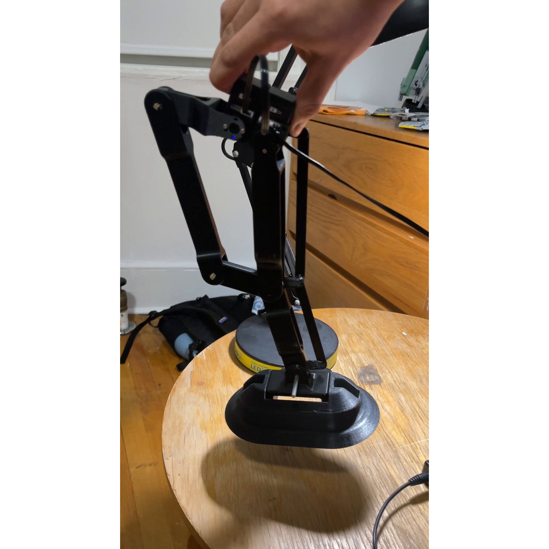
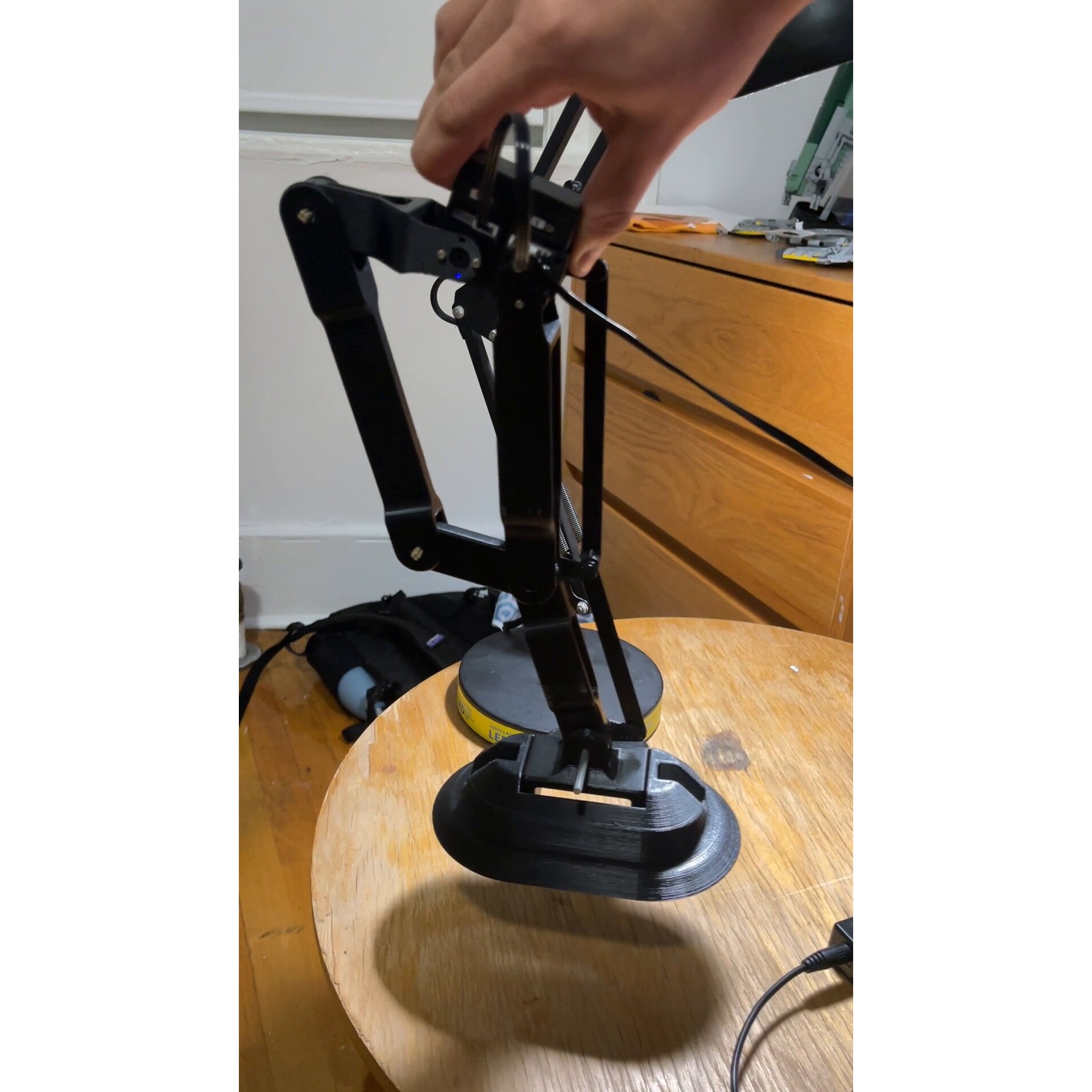
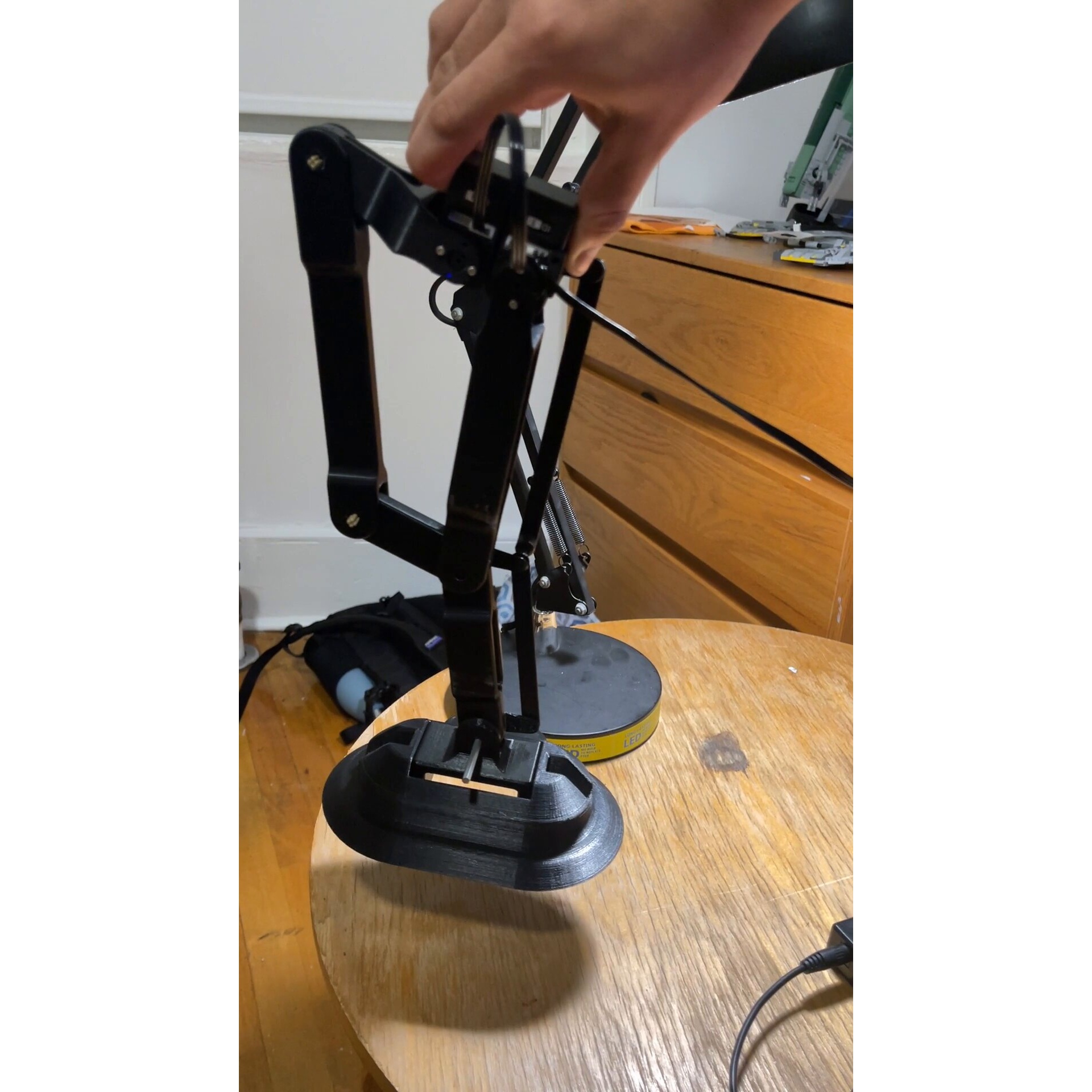
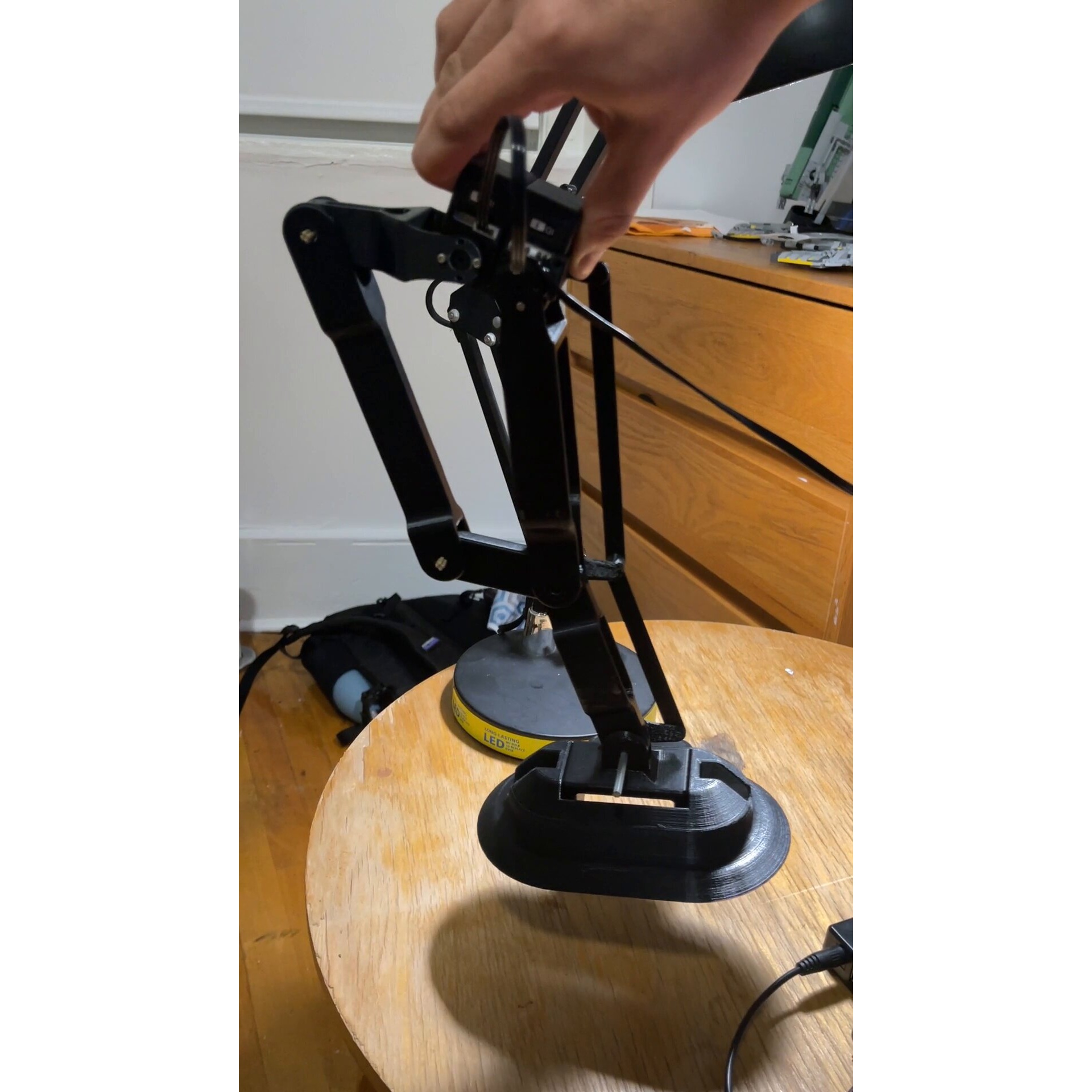
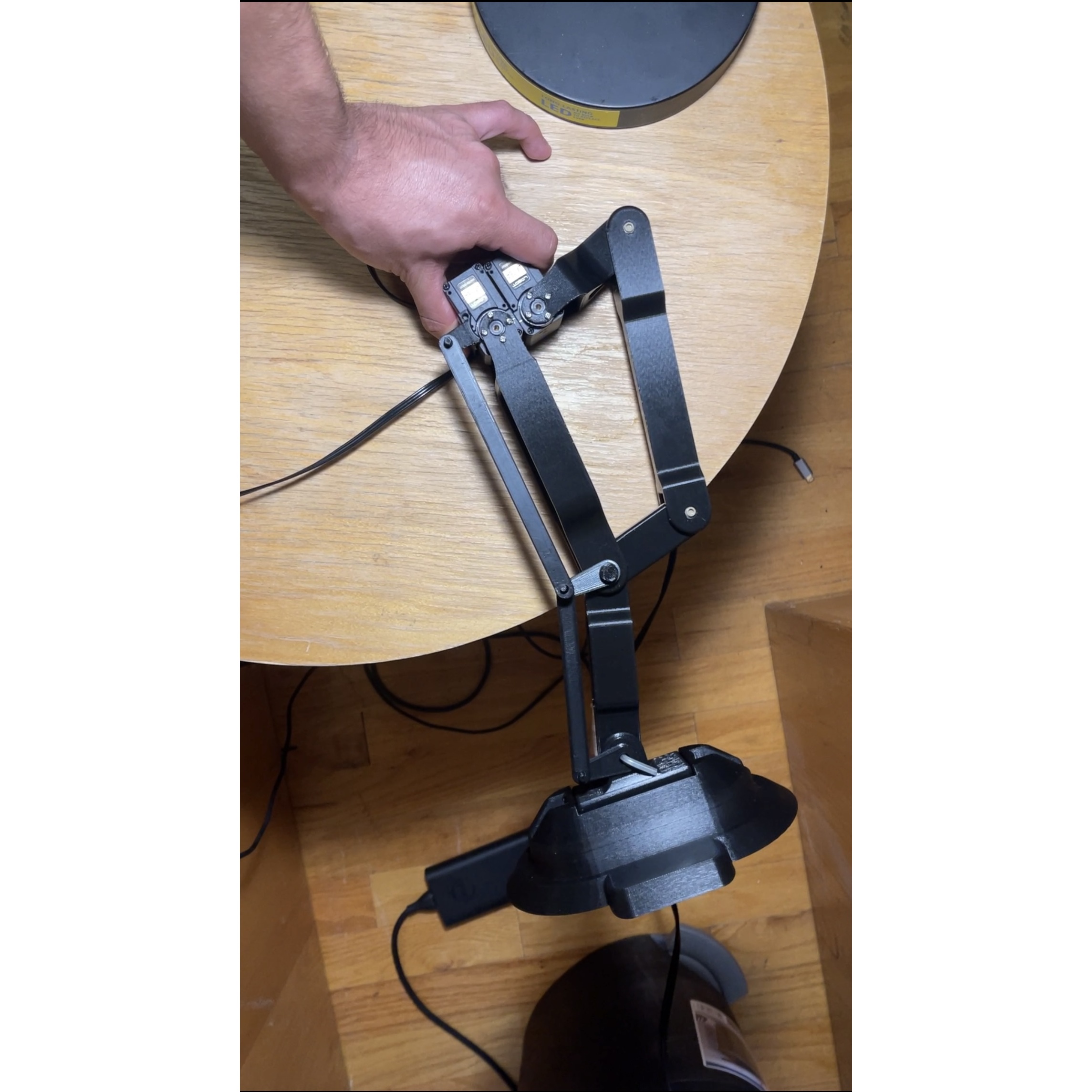
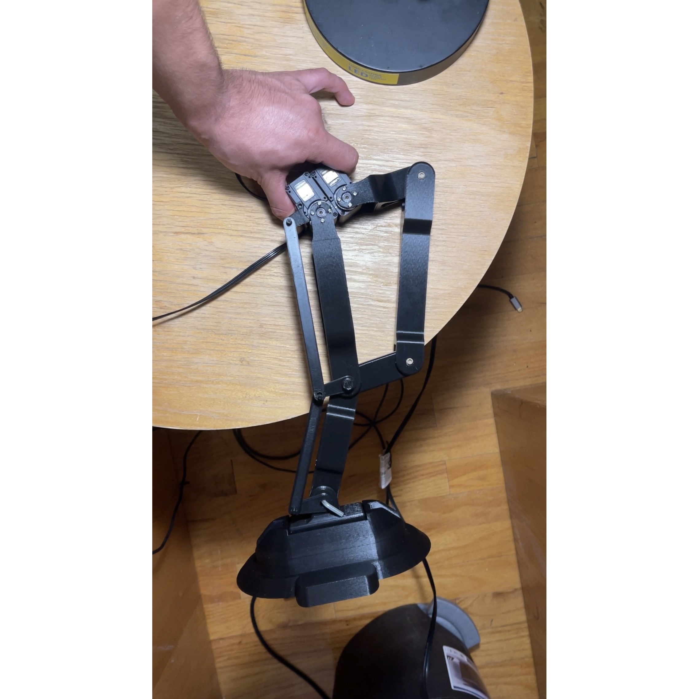
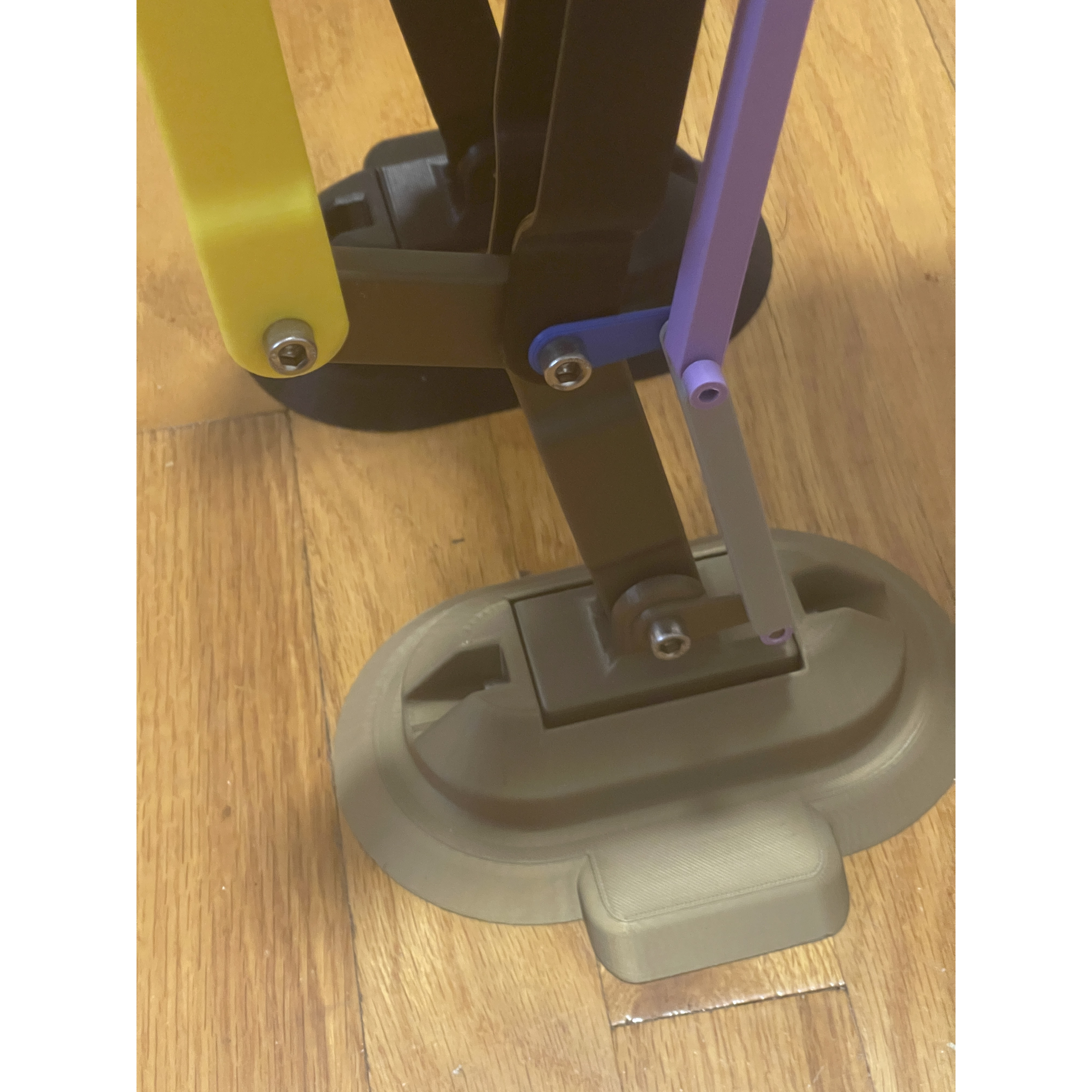
3D Printed Parts for the Leg
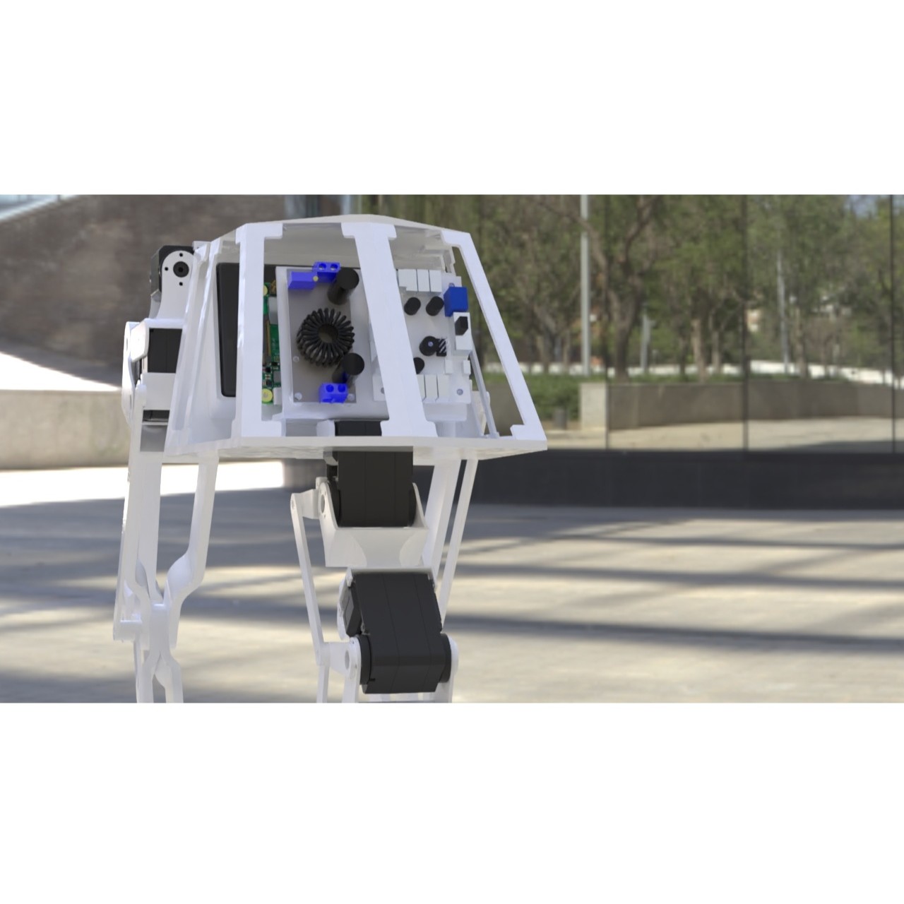
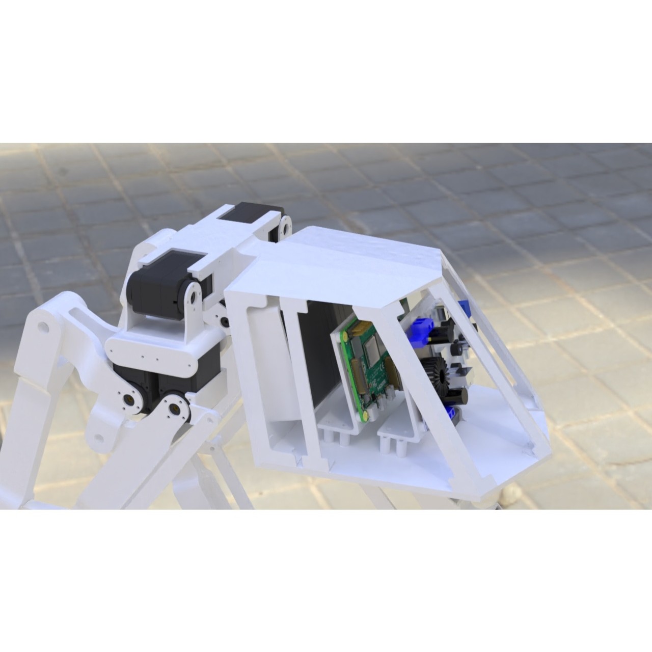
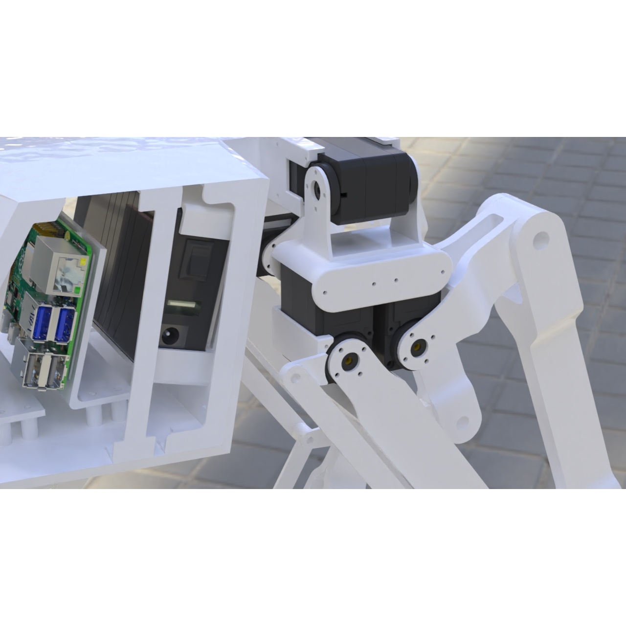
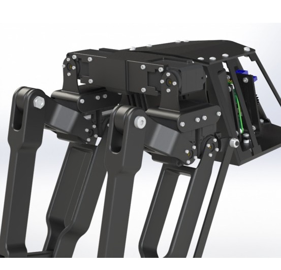
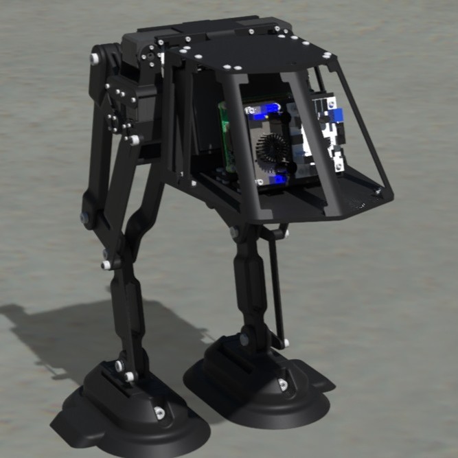
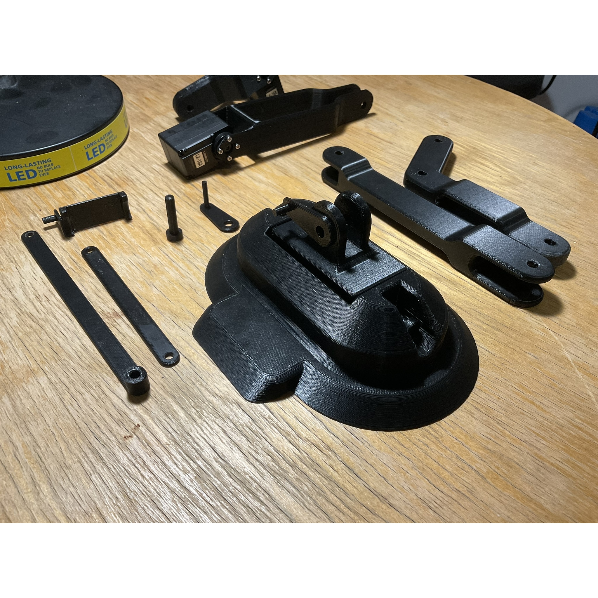
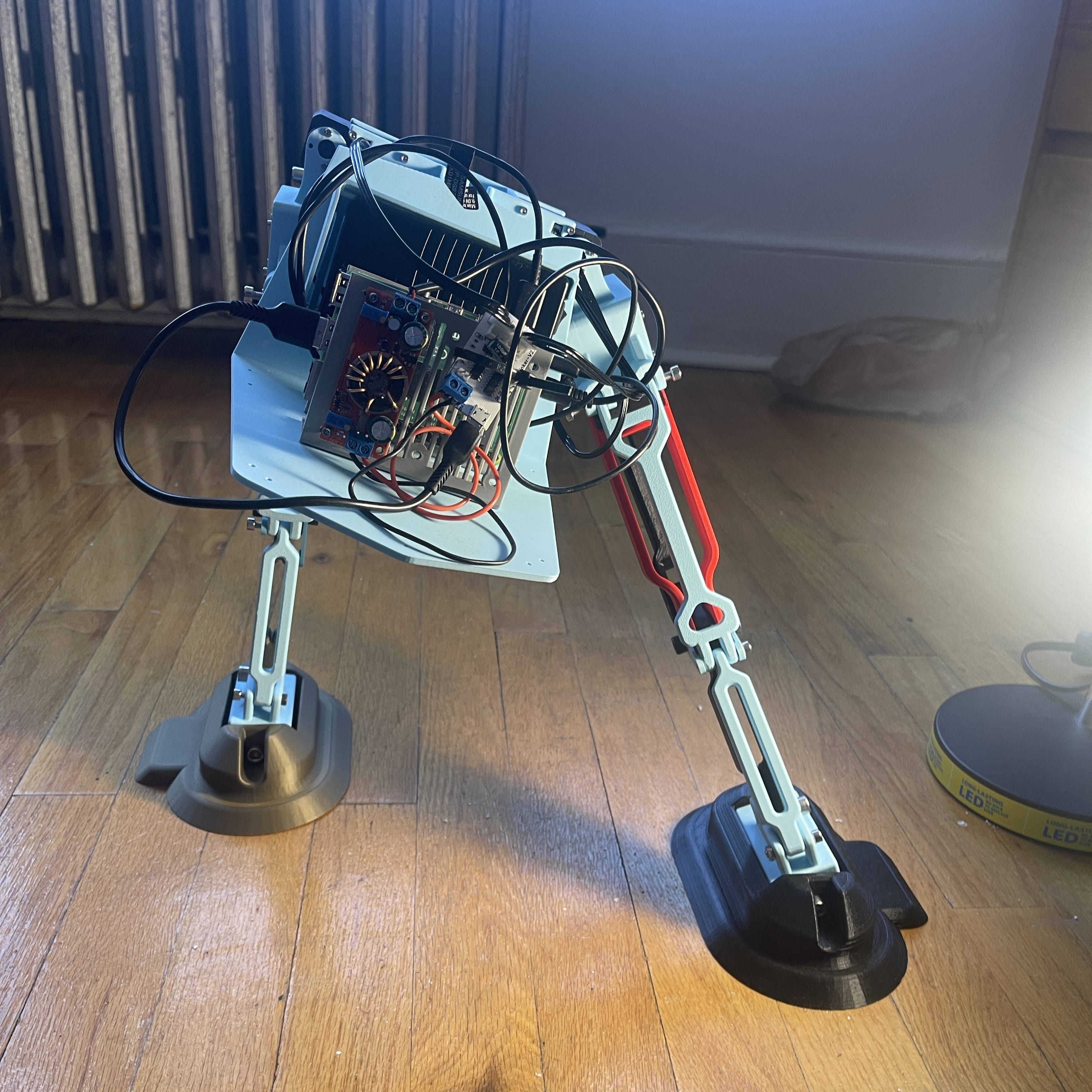
Week 7-8: Full Assembly & Basic Electronics Testing
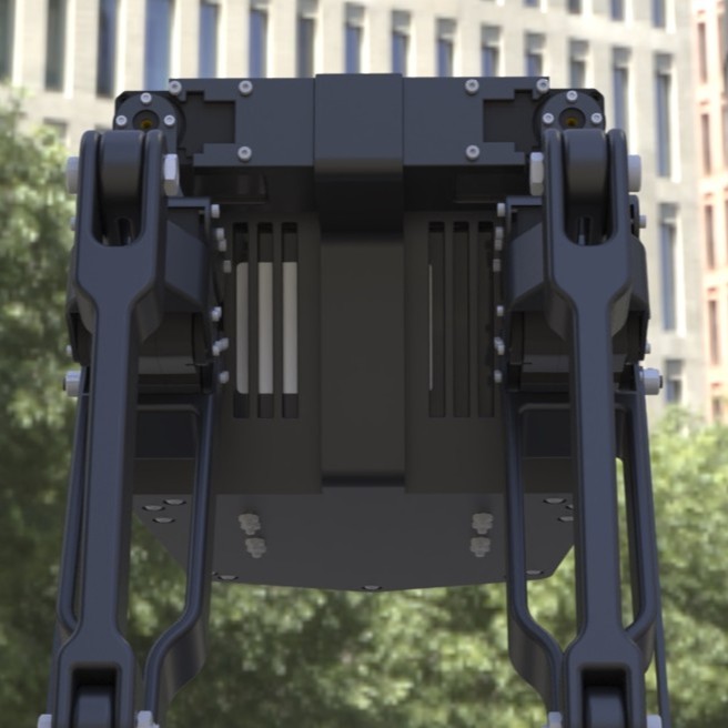
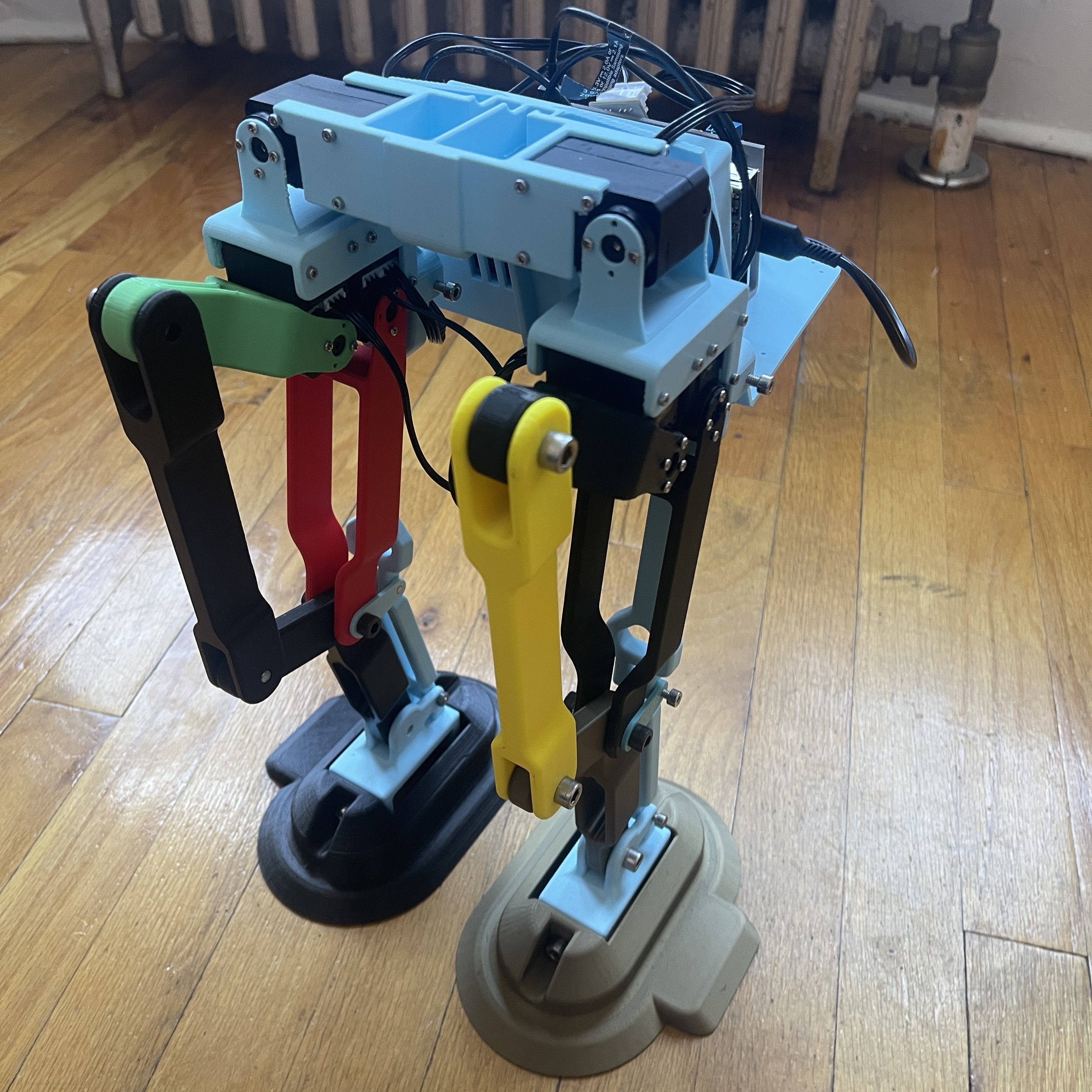
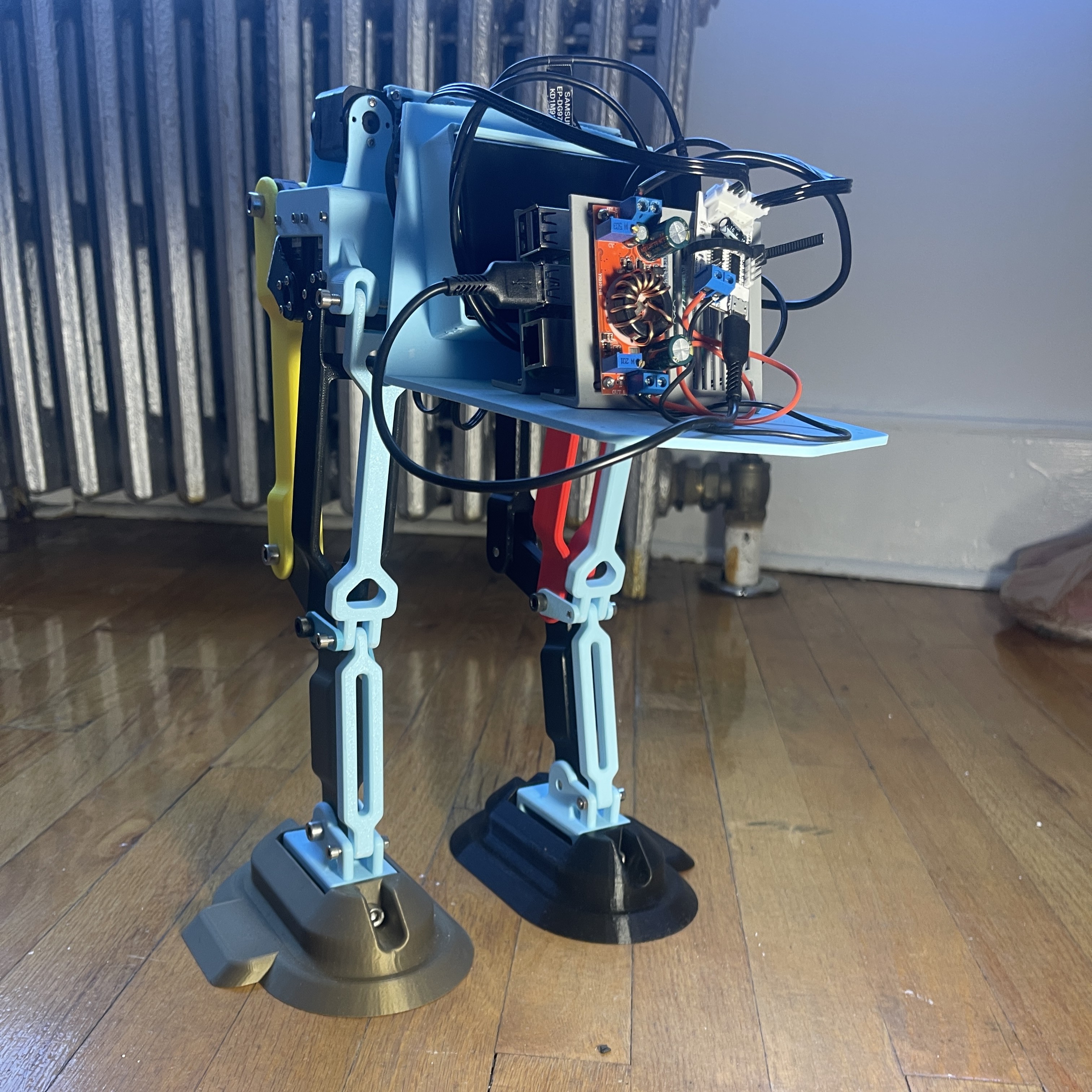
All 3D-printed parts such as the body, legs, and supporting structures were produced and combined with electronic components, bolts, screws, cables, and mounts according to the most recent CAD model. This marked the first time the entire design was realized as a complete robot rather than just partial assemblies.
A few issues emerged during assembly, such as form and fit problems caused by 3D printer tolerances, which were documented and addressed by updating the CAD and reprinting affected parts. These small iterations improved the accuracy of the build and integration of all modules.
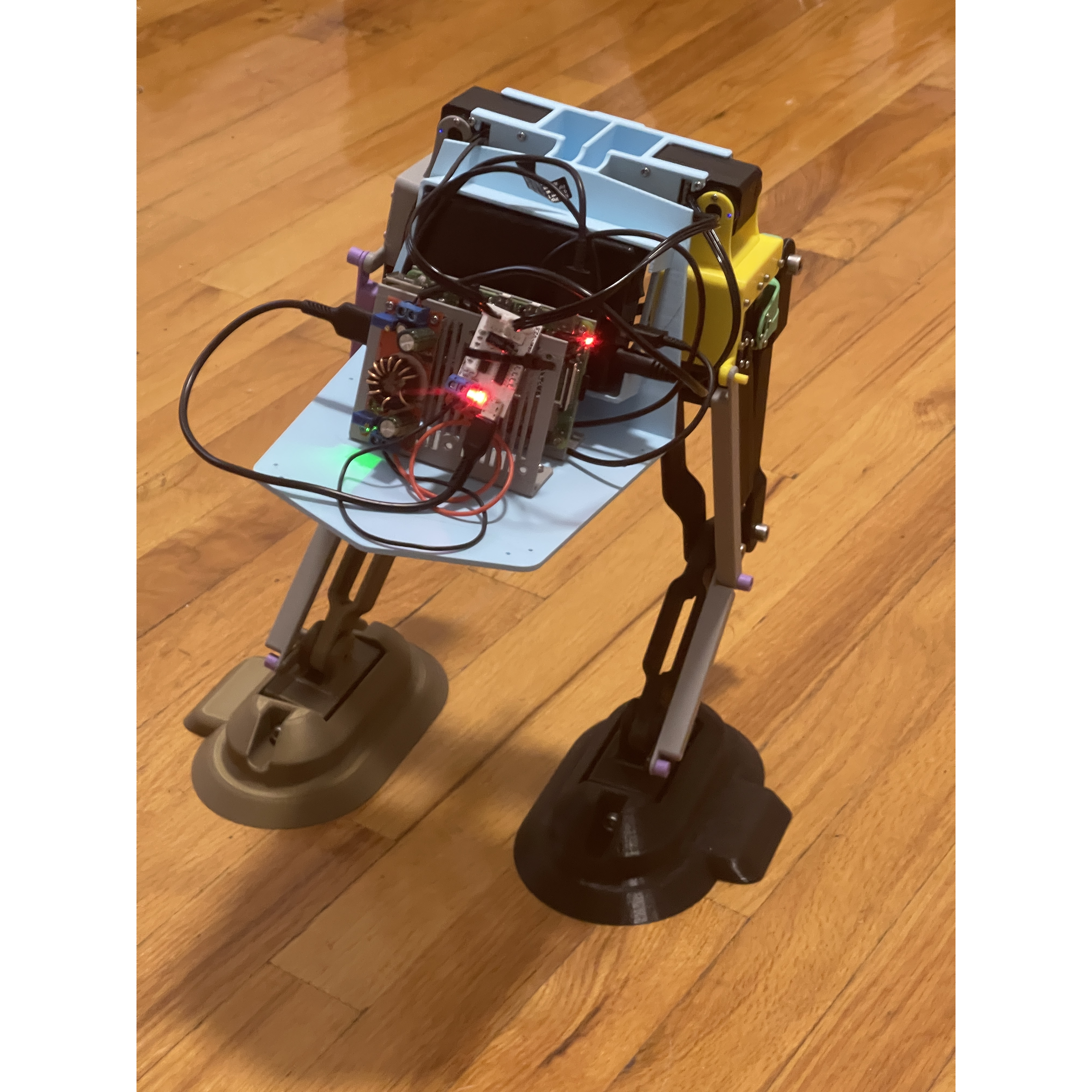
With the Raspberry Pi, battery, and controller on board, the system was powered and controlled directly from its onboard hardware. This allowed the robot to demonstrate its first powered motions as a complete unit. Check out the video of the first fully assembled robot in action.
These milestones confirmed the progress toward a functional robot and provided a strong foundation for the next stages of testing and refinement. Key specifications such as weight, dimensions, and overall power consumption were documented for future reference and comparison.
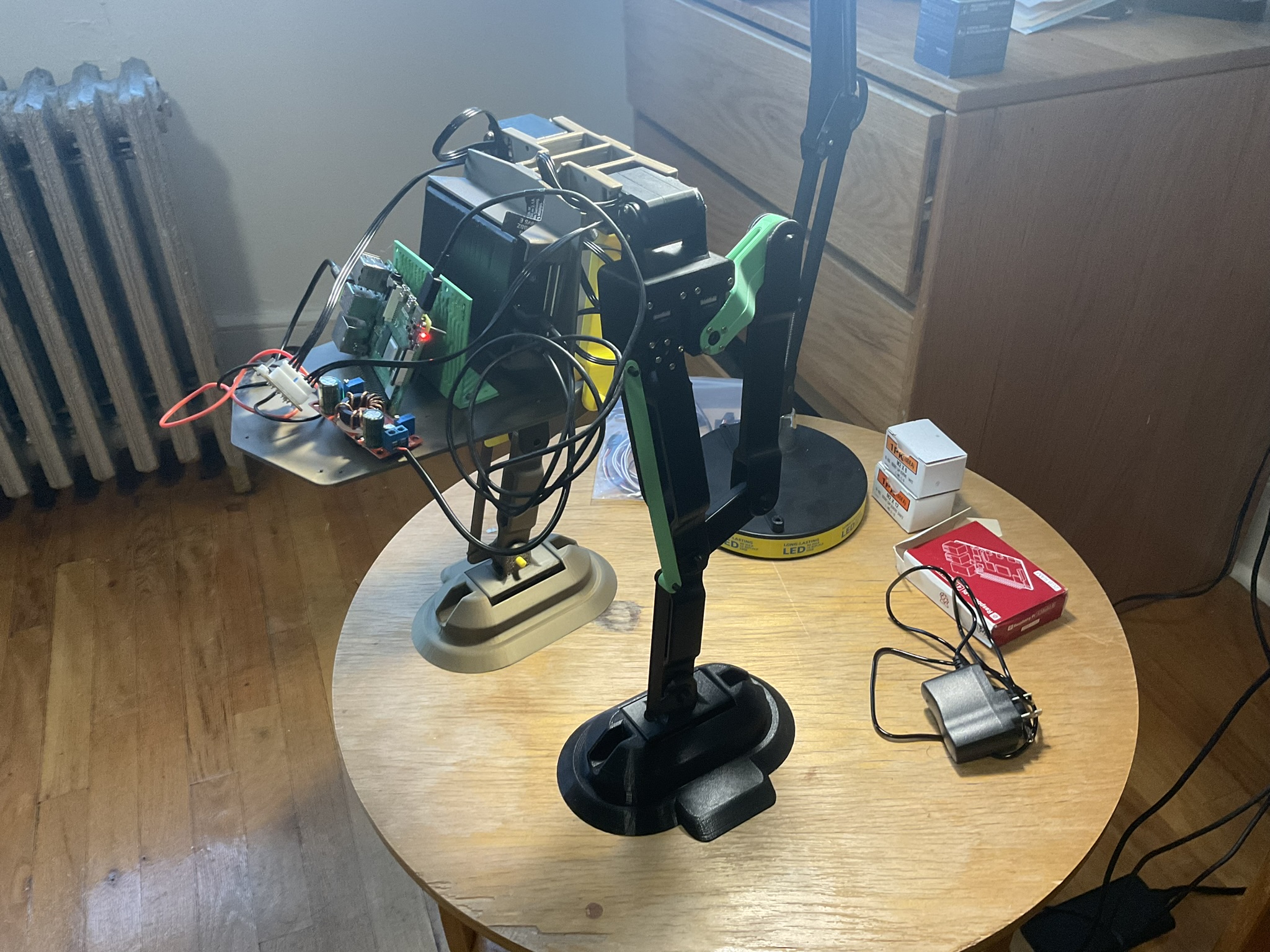
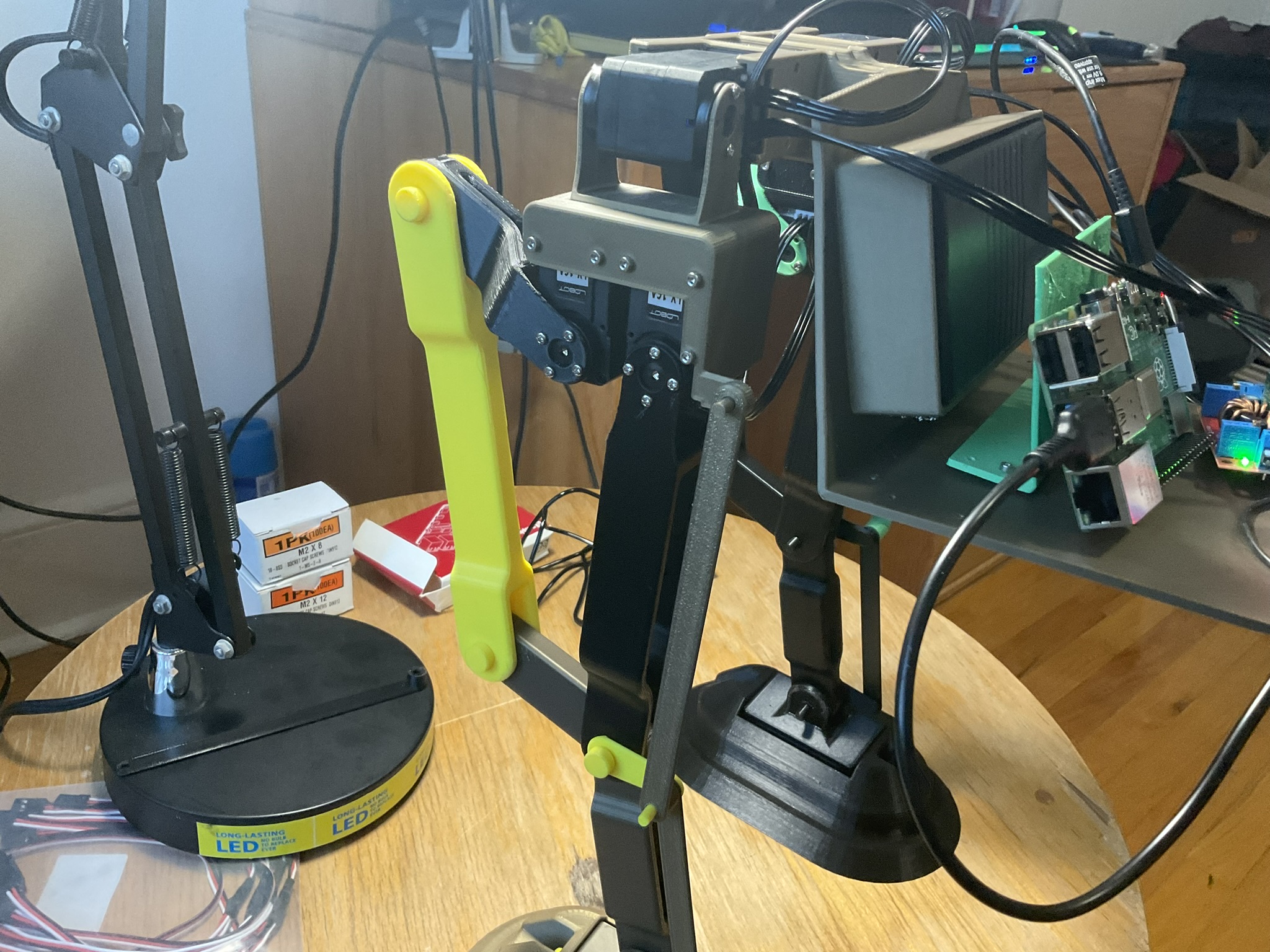
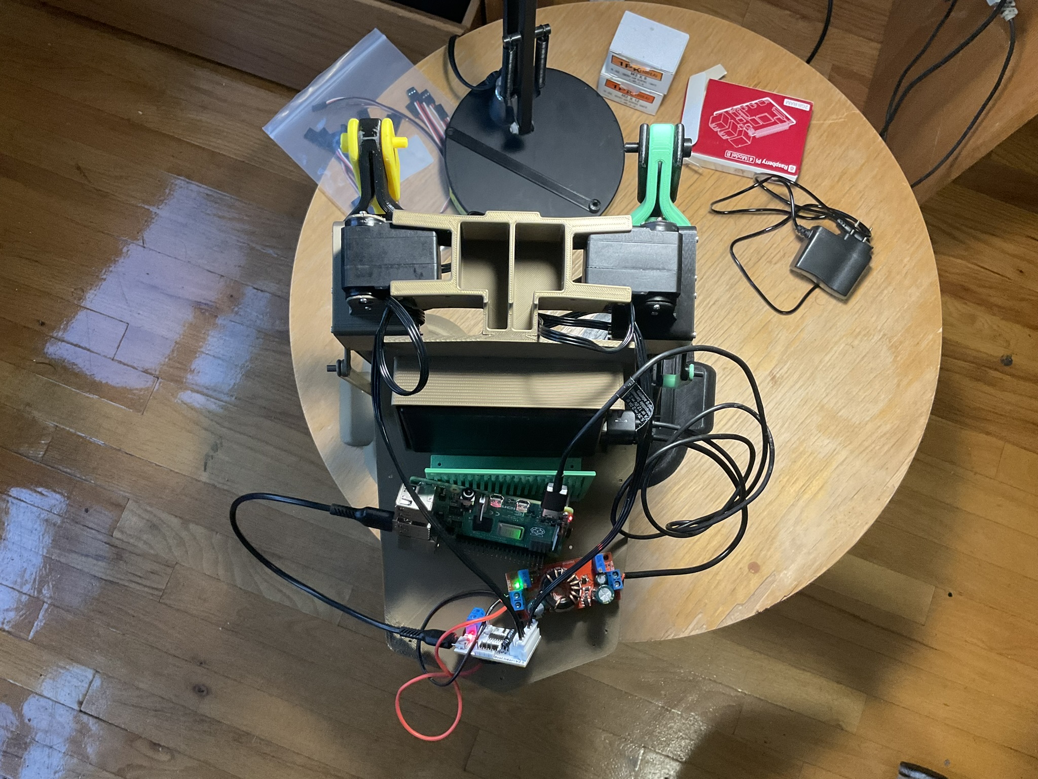
First Fully Assembled Robot
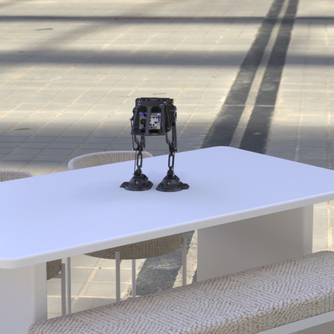
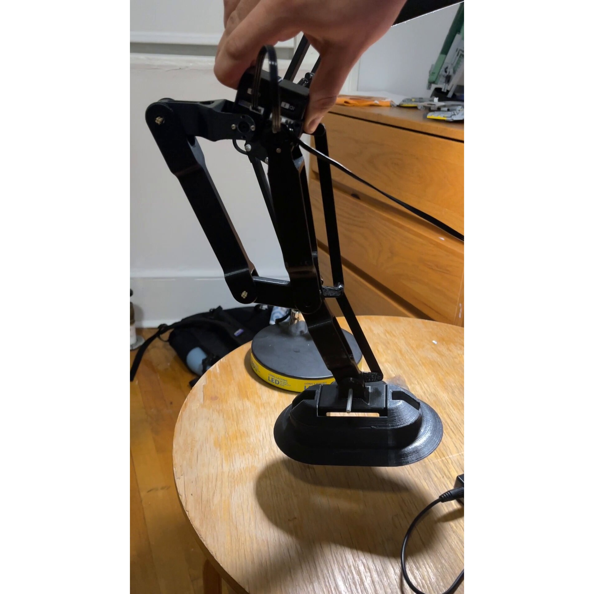
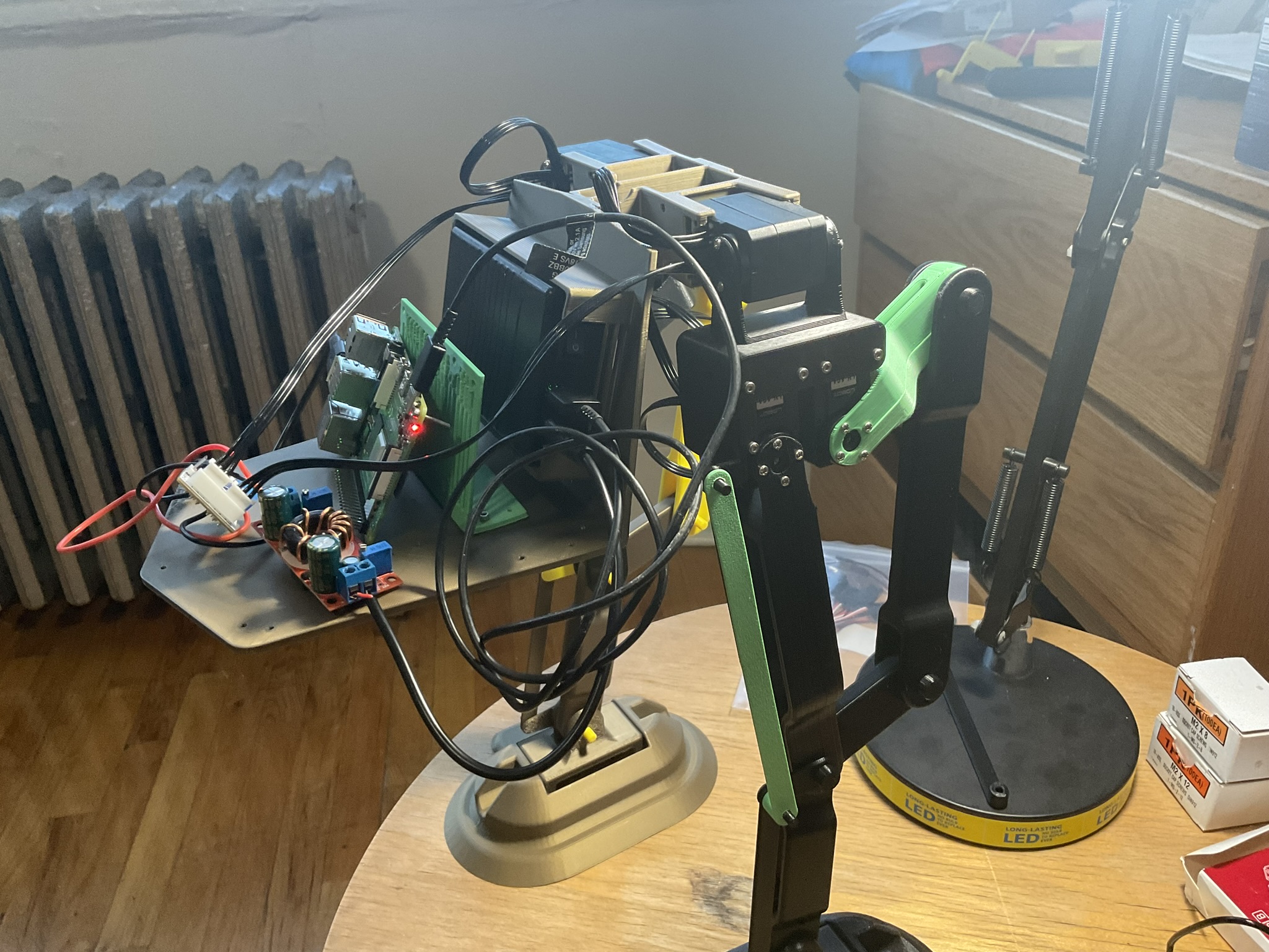
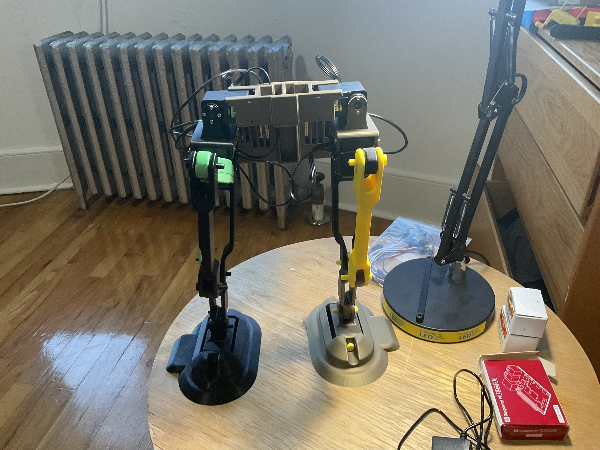
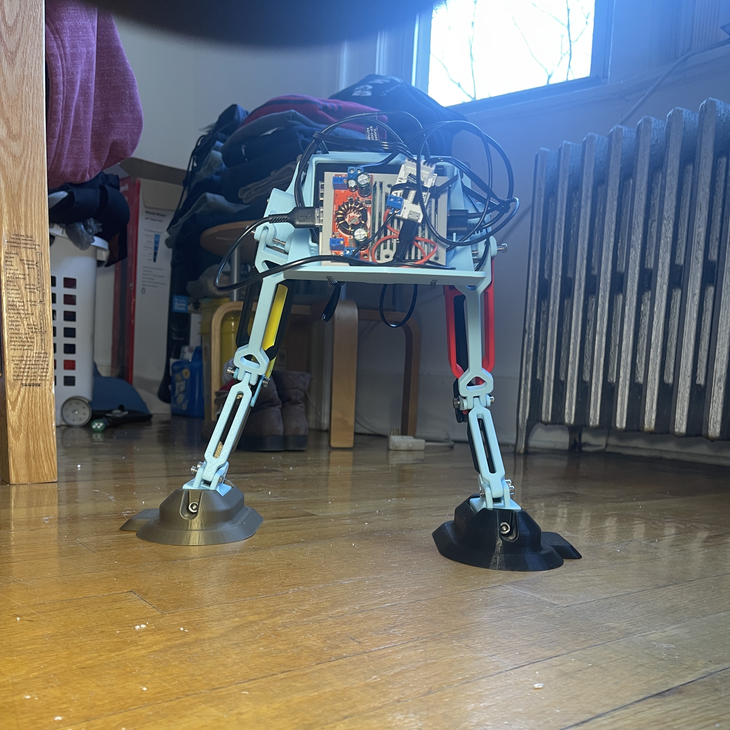
Week 9-10: Initial Gait Programming
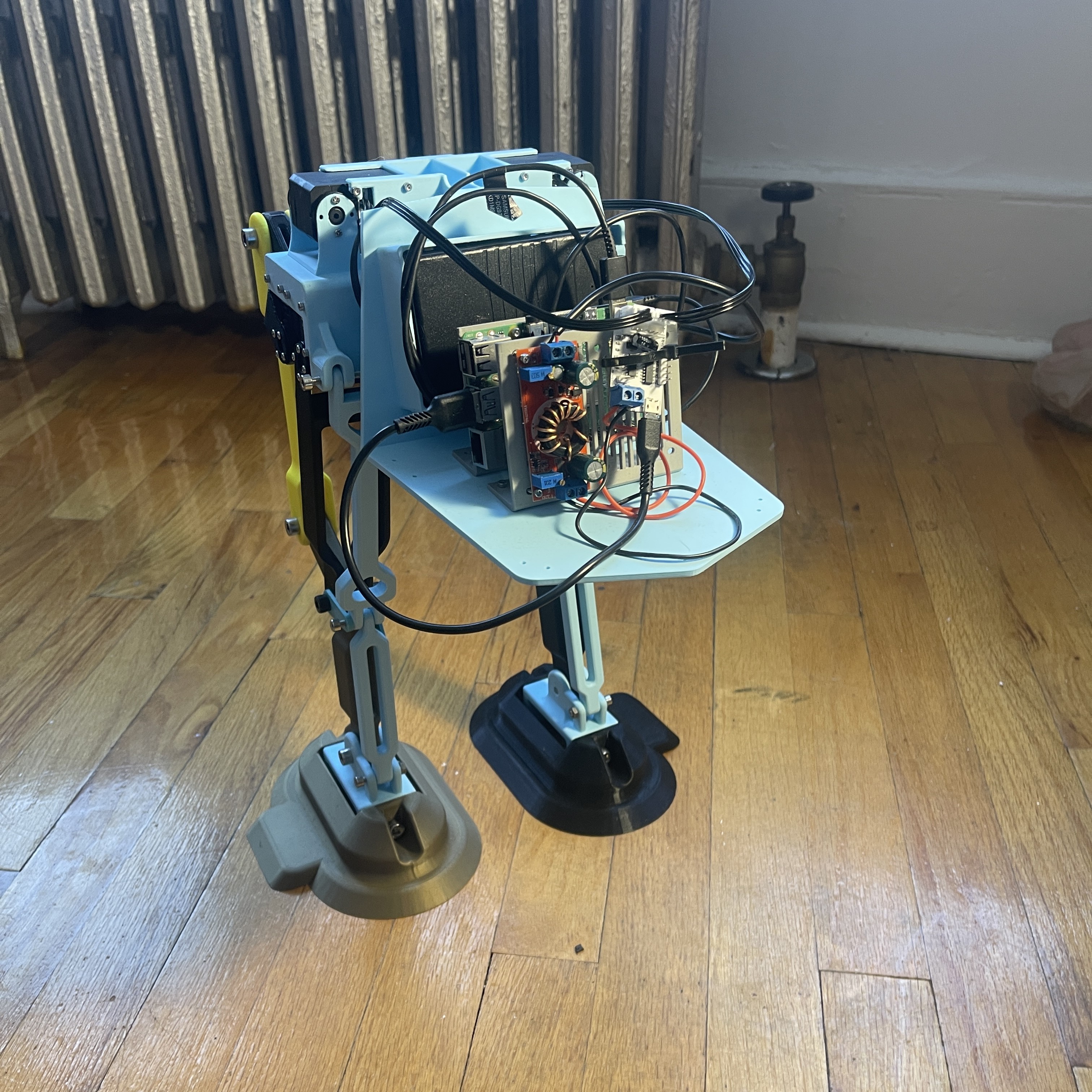
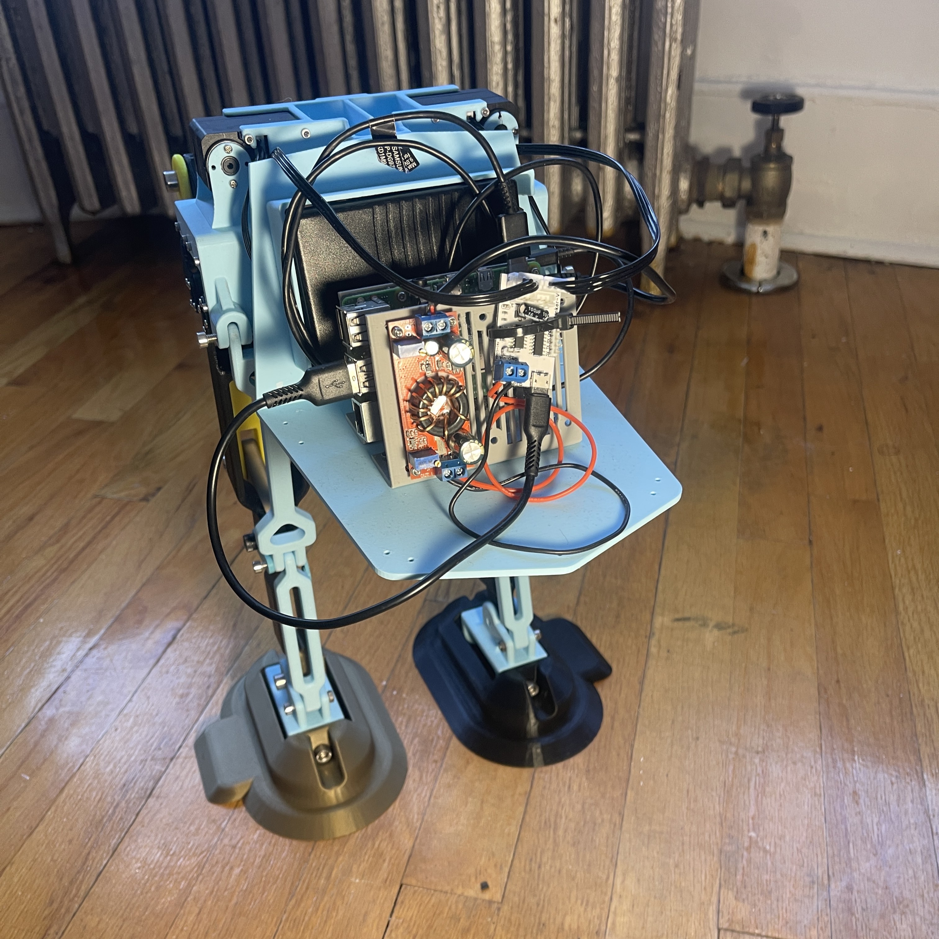
With the robot fully assembled and powered, the next step was to give it motion. Using the Raspberry Pi 4 Model B powered by the onboard battery, Python code was written and executed through a VNC server connection, allowing the robot to take its very first steps. All servo motors were routed and secured carefully to ensure proper control signals could be sent from the Raspberry Pi.
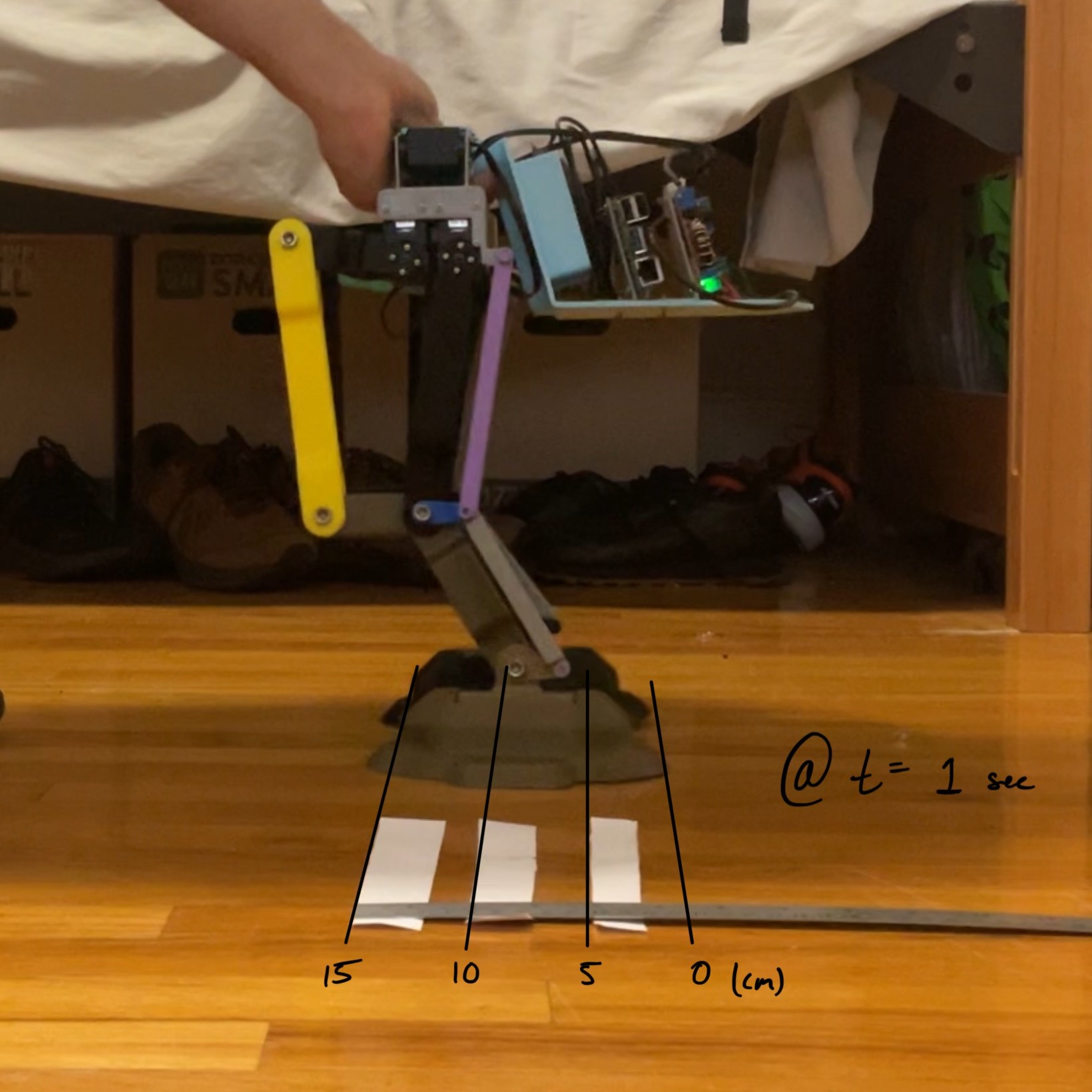
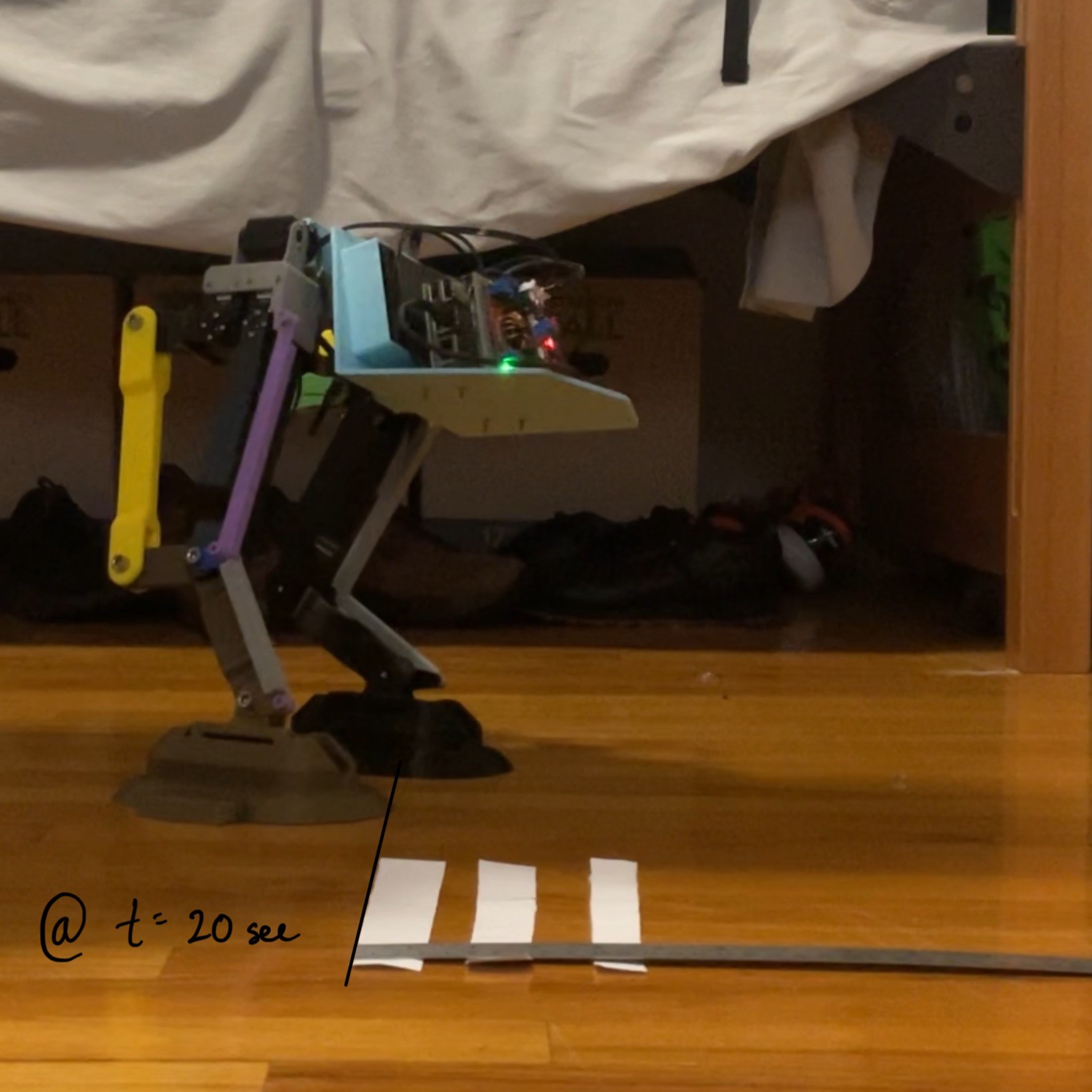
During the first walking trial, the robot successfully achieved locomotion but moved backwards instead of forwards. While this highlighted that the gait sequence was functional, it also showed that adjustments to the programmed motor angles and step timing were needed for future iterations. Performance measurements were taken during this first test: the robot traveled 15 cm in 19 seconds, giving a speed of approximately 0.789 cm/s. The motion required 16 cycles to cover this distance, or about 1 cm per cycle. Considering the robot’s foot length of 17 cm, this corresponds to roughly 0.0588 foot lengths per cycle.
This milestone marked an important transition from static assembly to true robotic behavior. Even though the gait sequence still requires refinement, the robot demonstrated untethered, powered walking for the first time. Check out the video of the robot’s first steps.
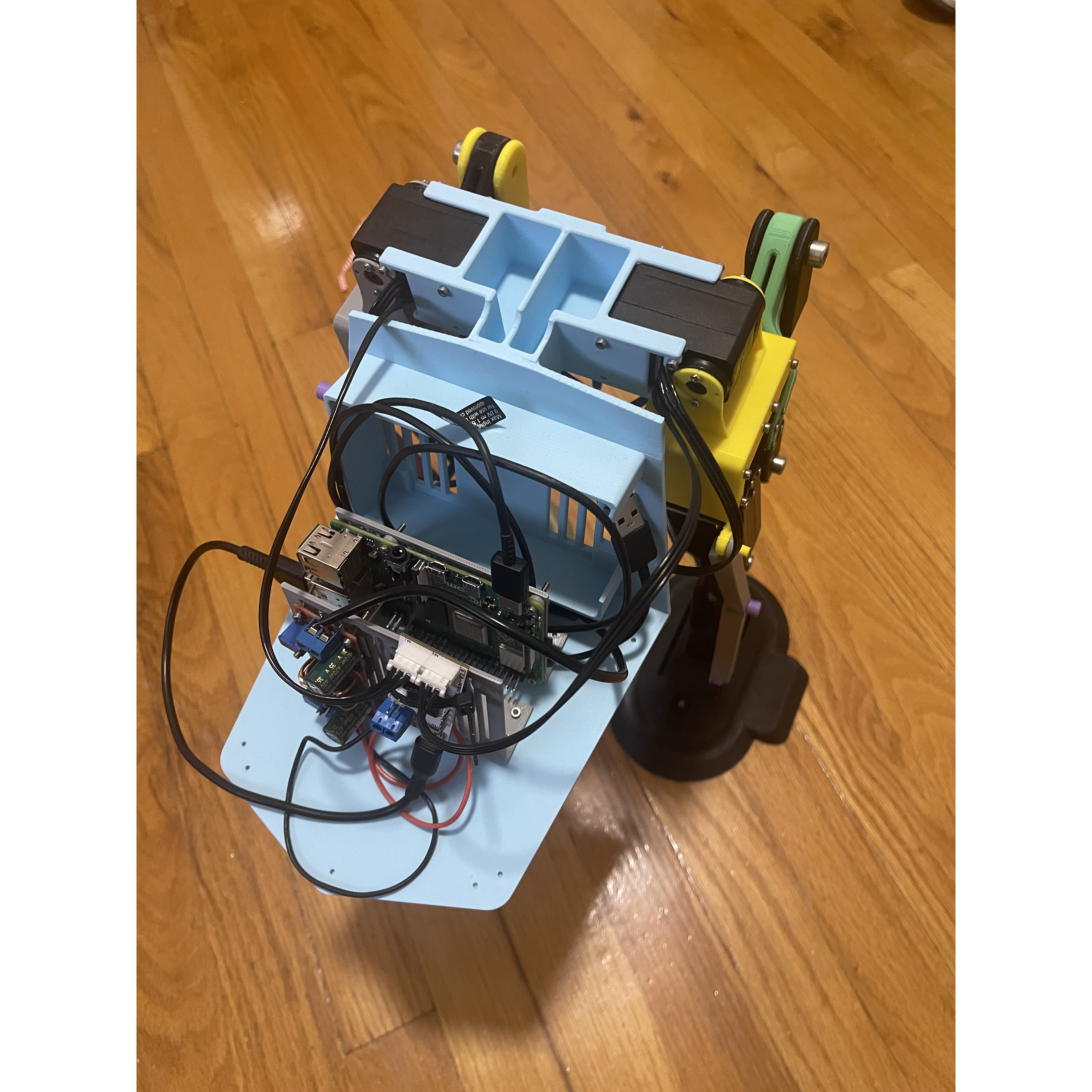
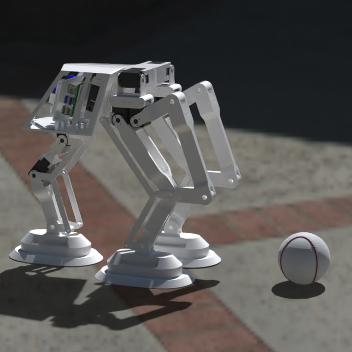
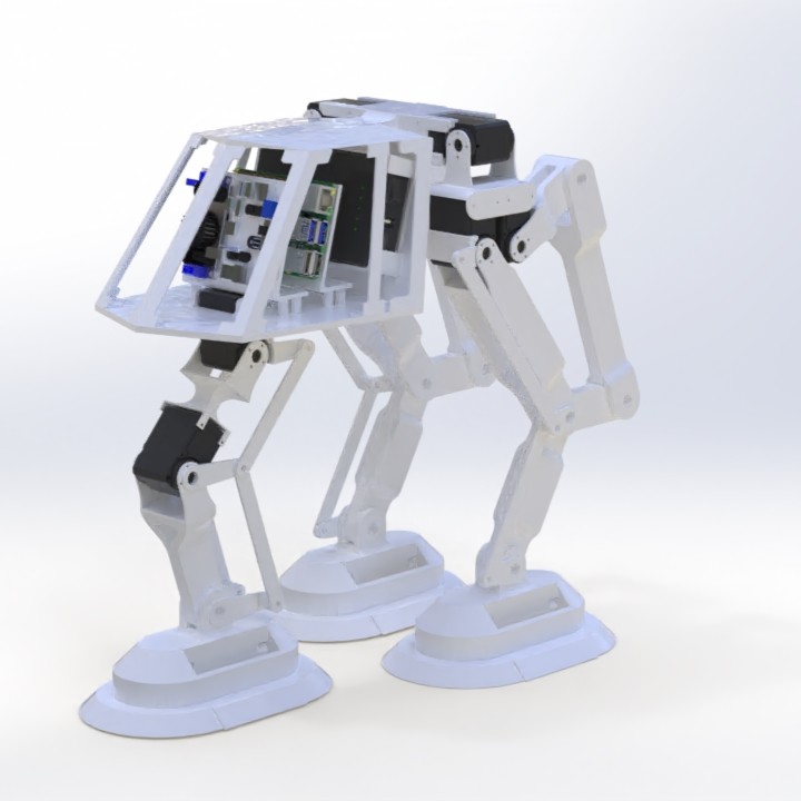
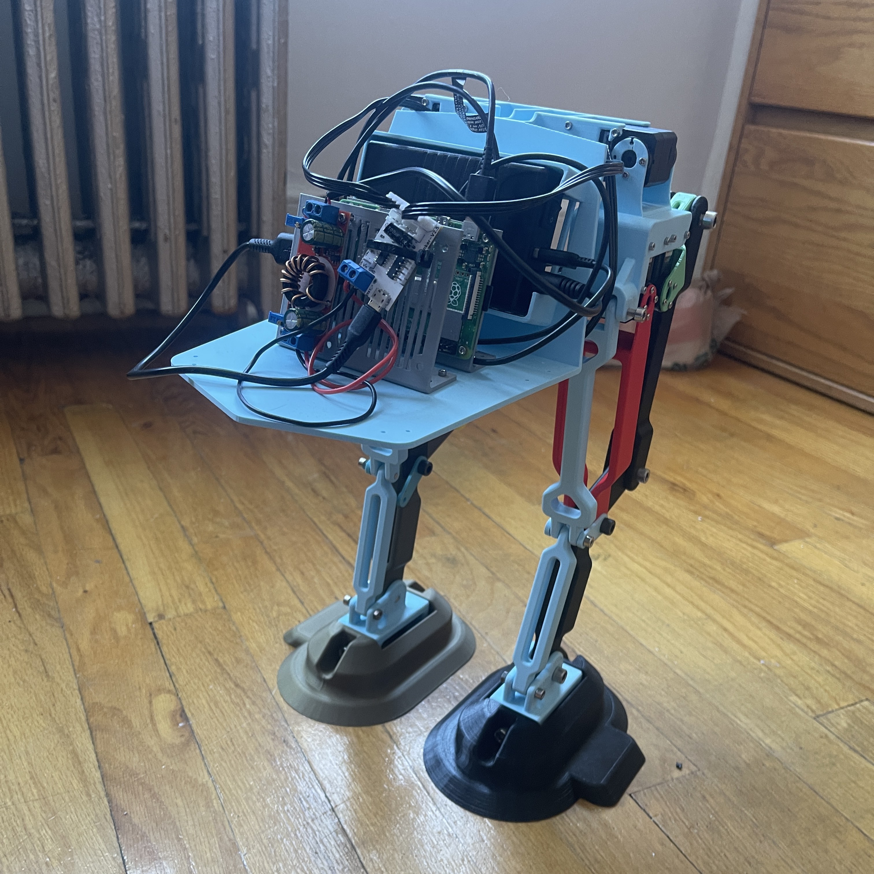
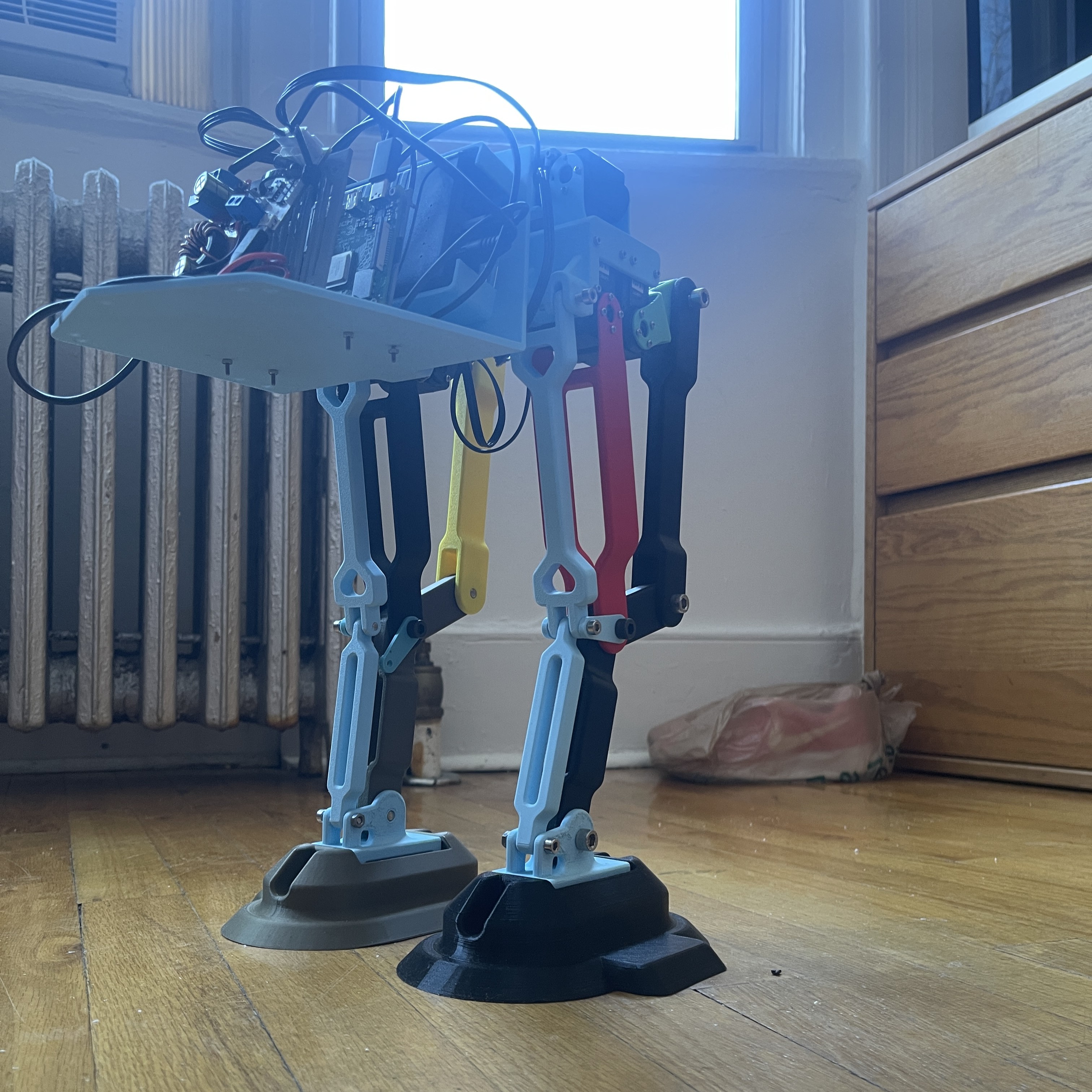
Second Version of the Fully Assembled Robot
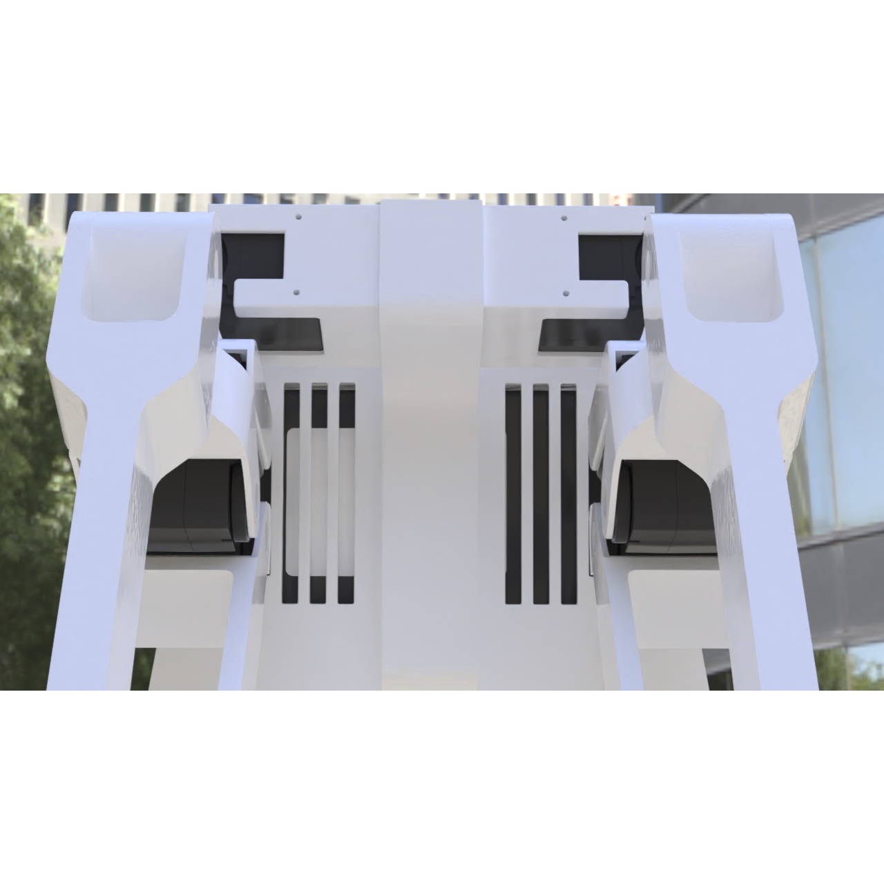
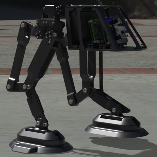
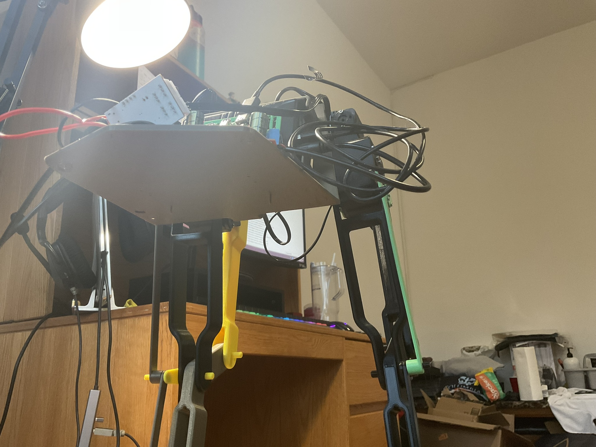
Week 11-12: Refinement & Final Adjustments
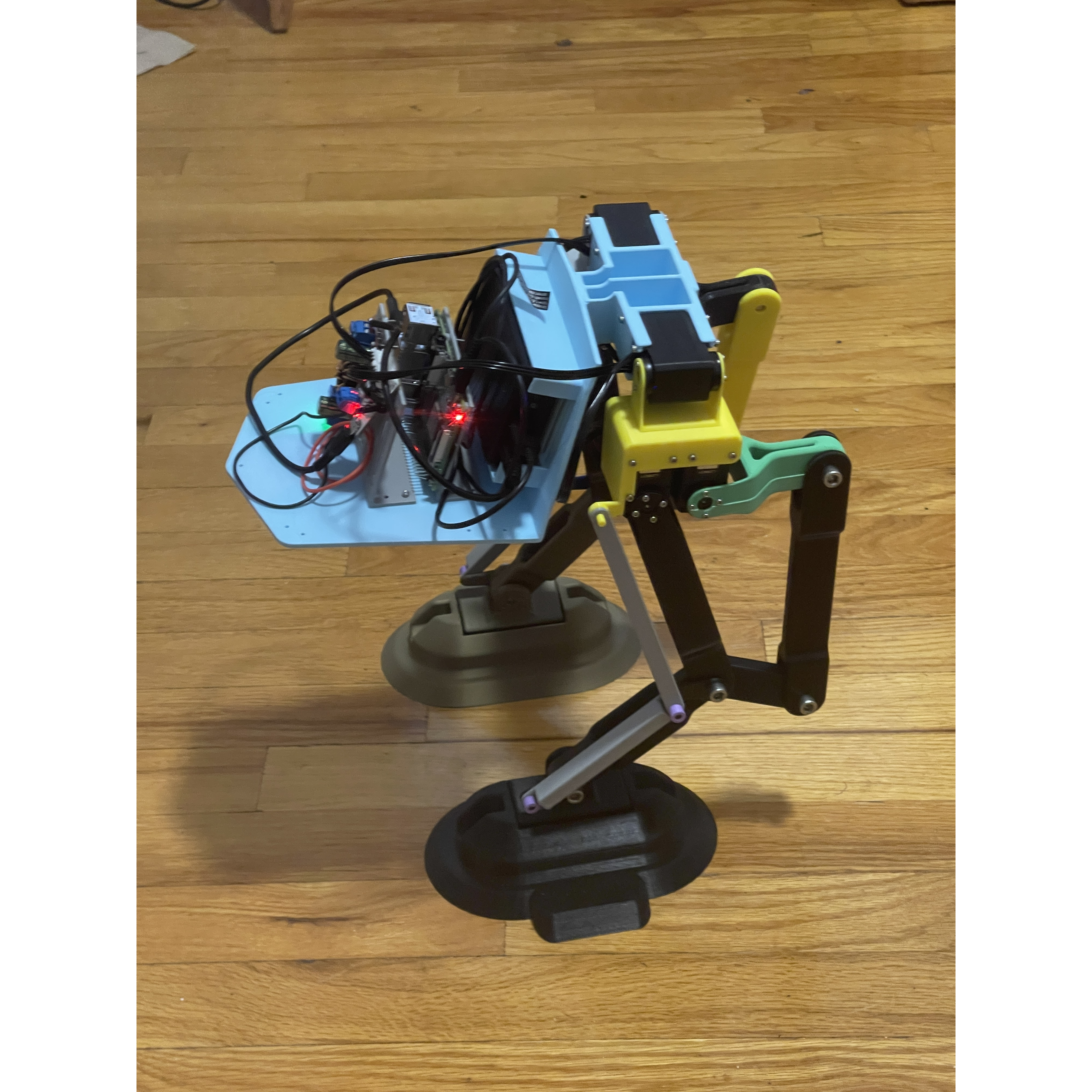
For the final stretch of the project, the robot’s legs were refined leading to improve its overall walking performance. One of the biggest issues in earlier iterations had been the weakness of the passive joints. They would often break, putting unnecessary strain on the motors. To fix this, the passive joints were redesigned and reinforced, giving the legs more strength while keeping them lightweight for locomotion.
The robot could stand upright at any point in the servo cycle (static stability) and maintained balance fairly well during motion (dynamic stability), though aggressive moves could still cause minor instability if the surface wasn’t perfectly flat. No sensors were used for feedback, meaning the gait was entirely pre-programmed and deterministic.
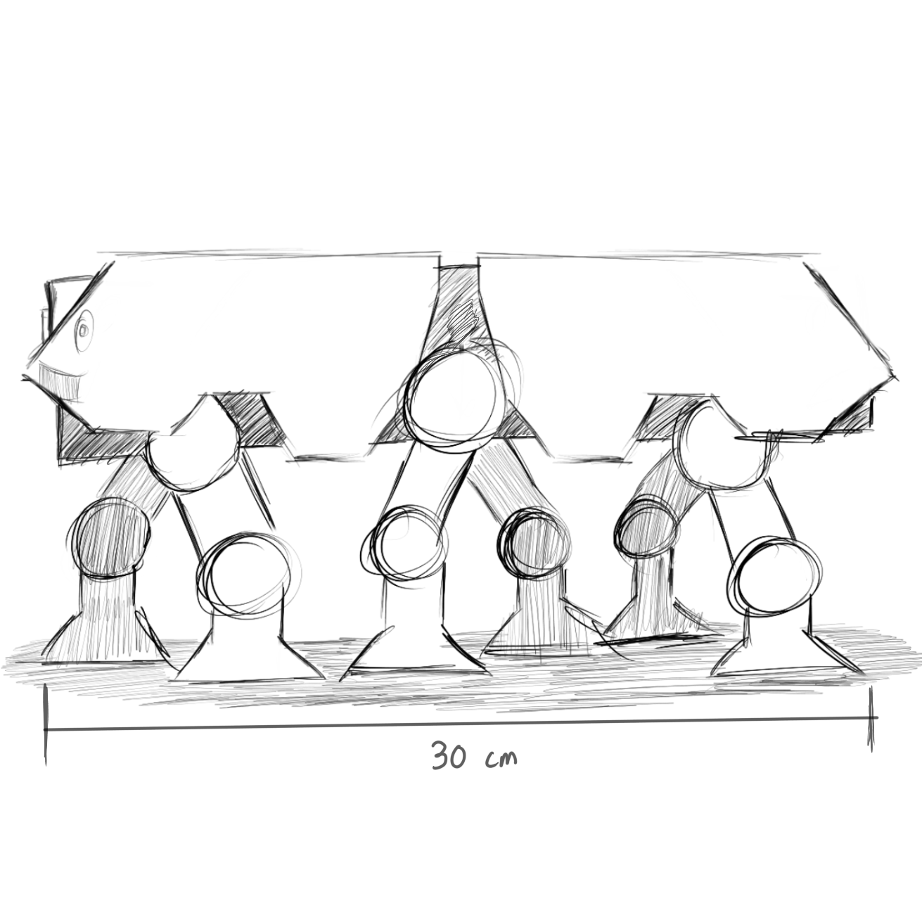
In terms of performance, the final round of testing showed a significant improvement in speed compared to earlier weeks. The robot was able to traverse 30 centimeters in 14.92 seconds, giving a maximum speed of 2.01 cm/s. A short video was recorded of the robot walking alongside a tape measure to capture the performance.
Overall, the refinements to the leg design and passive joints, along with correct gait programming, brought the project to a satisfying conclusion.
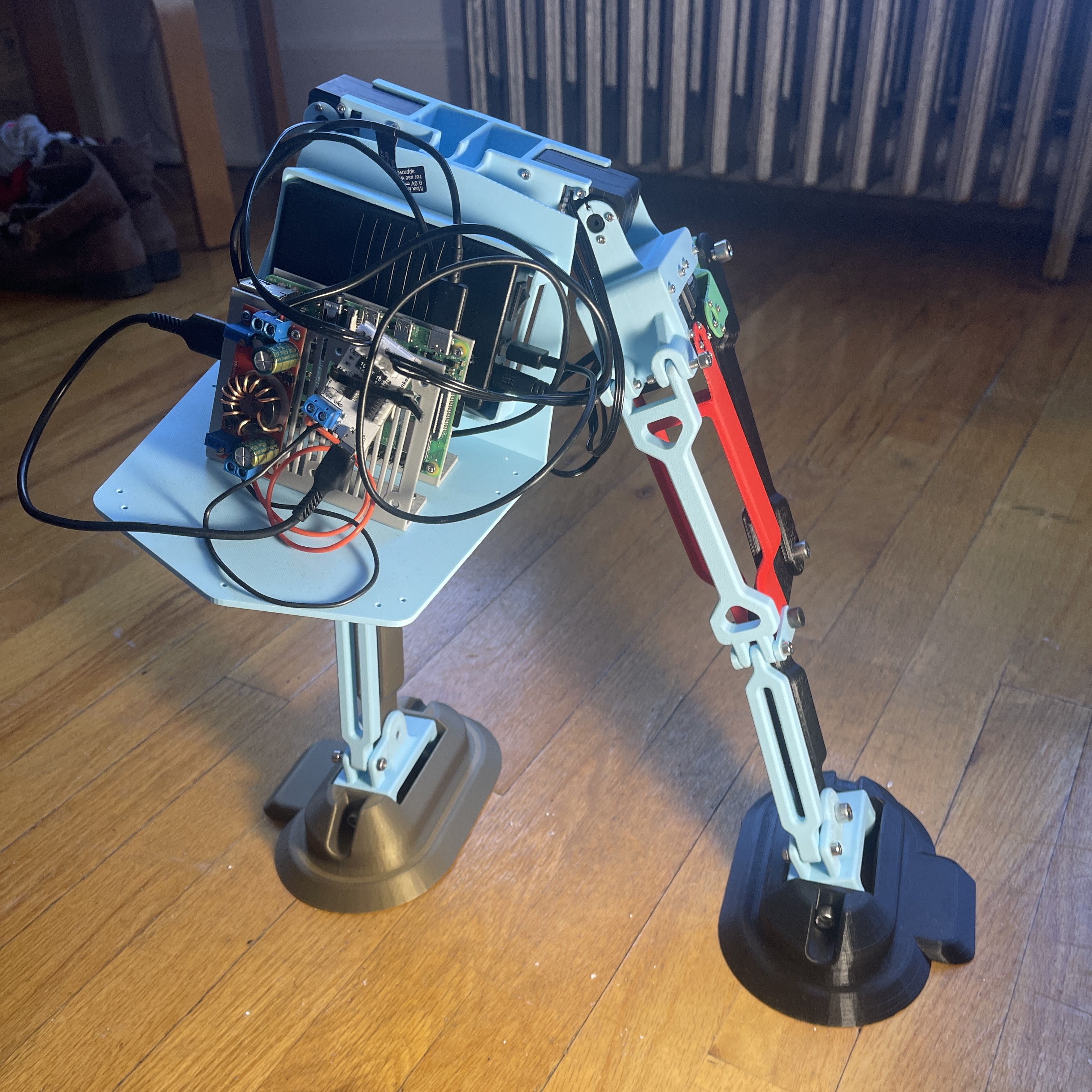
Final Version of the Fully Assembled Robot
My Journey Video
This video documents the entire process of designing, prototyping, and building a legged robot from the ground up. From initial sketches to CAD modeling, 3D printing, assembly, and programming, the project challenged me to integrate mechanics, electronics, and software to create a functional walking robot. Watch months of work come together in a final, working design.