Hydraulic Press System Analysis
Project Overview
This project analyzed the piping system of a hydraulic press to determine an appropriately sized pump, return line diameter, and pressure-relief valve. The system was evaluated using conservation of mass, the energy equation, and fluid mechanics principles to calculate head availability, head losses, and Net Positive Suction Head (NPSH).
Engineering decisions were validated through analytical calculations and component research to ensure the system satisfied flowrate requirements (20–30 gpm), prevented cavitation, minimized cost, and maintained reliable operation.
Hydraulic System Configuration
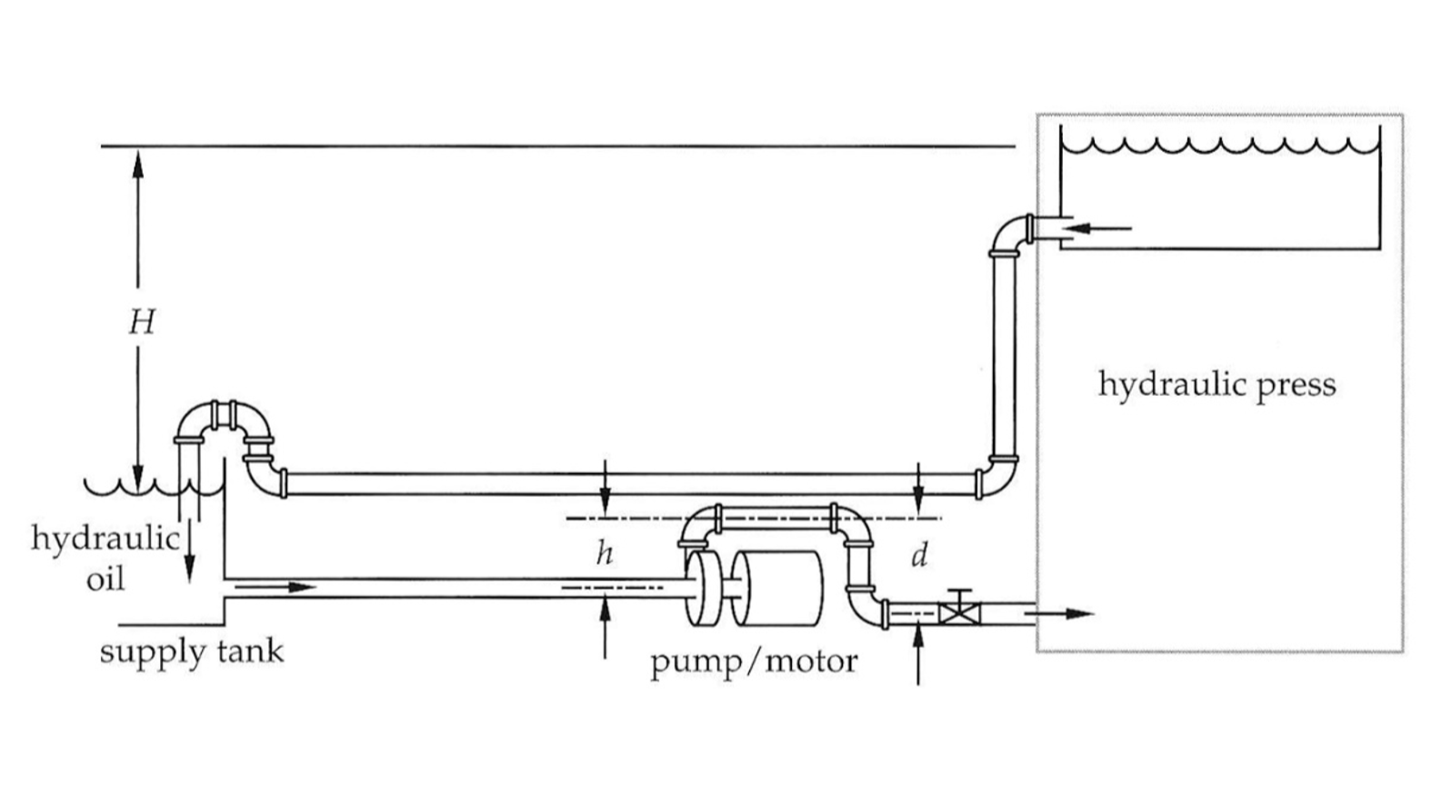
The hydraulic press system consisted of a supply tank, pump inlet line, outlet line, elevated discharge tank, and return line. Hydraulic oil circulated through the system while meeting specified pressure and flow constraints.
- Supply tank capacity: 10 gallons
- Supply tank cross-sectional area: 2.5 m2
- Required flowrate: 20–30 gpm
- Operating pressure: 30 psia
- Inlet pipe length: 2.5 m (2" schedule 40 PVC)
- Outlet pipe length: 6 m (1.5" schedule 40 PVC)
- Return line length: 12 m
- Height difference between tanks: 6 ft
Engineering Approach
The system was analyzed using steady-state incompressible flow assumptions. Key calculations included:
- Energy equation and conservation of mass
- Head availability from tank elevations
- Net Positive Suction Head (NPSH) analysis
- Pipe head losses due to friction and fittings
- Reynolds number and friction factor estimation
- Cost and performance comparison of commercial components
Pump Selection
Head availability and NPSH calculations were performed to ensure proper pump operation and prevent cavitation.
Available Head
6.54 ft total head available from system elevation and tank geometry.
NPSH Available
80.5 ft, significantly exceeding required values.
Selected Pump
March TE-7.5P-MD magnetic drive pump.
Return Line Design
The return line diameter was determined by evaluating velocity, head losses from friction and pipe fittings, and Reynolds number assuming laminar flow conditions.
- Minimum required diameter: 3.125 in
- Recommended sizes: 3.5–4 in schedule 40 PVC
- Larger diameter reduces head loss and enables gravity-driven return flow
- 4-inch pipe selected for lower cost and availability
Flow Regulation Strategy
A valve was required to regulate flow below 30 gpm while minimizing system losses. Head loss analysis and flow requirements indicated that a full-width ball valve provided the best balance of performance and cost.
- Low friction loss coefficient
- High flow capacity
- Minimal maintenance and leakage
- No need for fine throttling control
Final Design Summary
Pump
March TE-7.5P-MD Magnetic Drive Pump
Return Line
4-inch Schedule 40 PVC
Valve
Full-width ball valve
Key Engineering Takeaways
- Applied fluid mechanics principles to real system design
- Performed NPSH and cavitation analysis
- Modeled pipe flow and head losses
- Selected commercial components based on performance and cost
- Validated engineering decisions through quantitative analysis